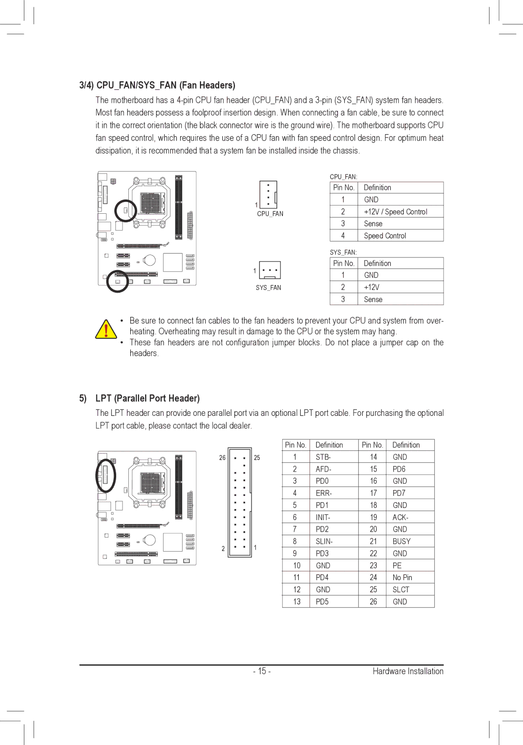
3/4) CPU_FAN/SYS_FAN (Fan Headers)
The motherboard has a
1
CPU_FAN
1
SYS_FAN
CPU_FAN:
Pin No. Definition
1GND
2+12V / Speed Control
3Sense
4Speed Control
SYS_FAN:
Pin No. Definition
1GND
2+12V
3Sense
•Be sure to connect fan cables to the fan headers to prevent your CPU and system from over- heating. Overheating may result in damage to the CPU or the system may hang.
•These fan headers are not configuration jumper blocks. Do not place a jumper cap on the headers.
5)LPT (Parallel Port Header)
The LPT header can provide one parallel port via an optional LPT port cable. For purchasing the optional LPT port cable, please contact the local dealer.
26
2
| Pin No. | Definition | Pin No. | Definition | |
25 | 1 | STB- | 14 | GND | |
| 2 | AFD- | 15 | PD6 | |
| 3 | PD0 | 16 | GND | |
| 4 | ERR- | 17 | PD7 | |
| 5 | PD1 | 18 | GND | |
| 6 | INIT- | 19 | ACK- | |
| 7 | PD2 | 20 | GND | |
1 | 8 | SLIN- | 21 | BUSY | |
9 | PD3 | 22 | GND | ||
| |||||
| 10 | GND | 23 | PE | |
| 11 | PD4 | 24 | No Pin | |
| 12 | GND | 25 | SLCT | |
| 13 | PD5 | 26 | GND |
- 15 - | Hardware Installation |