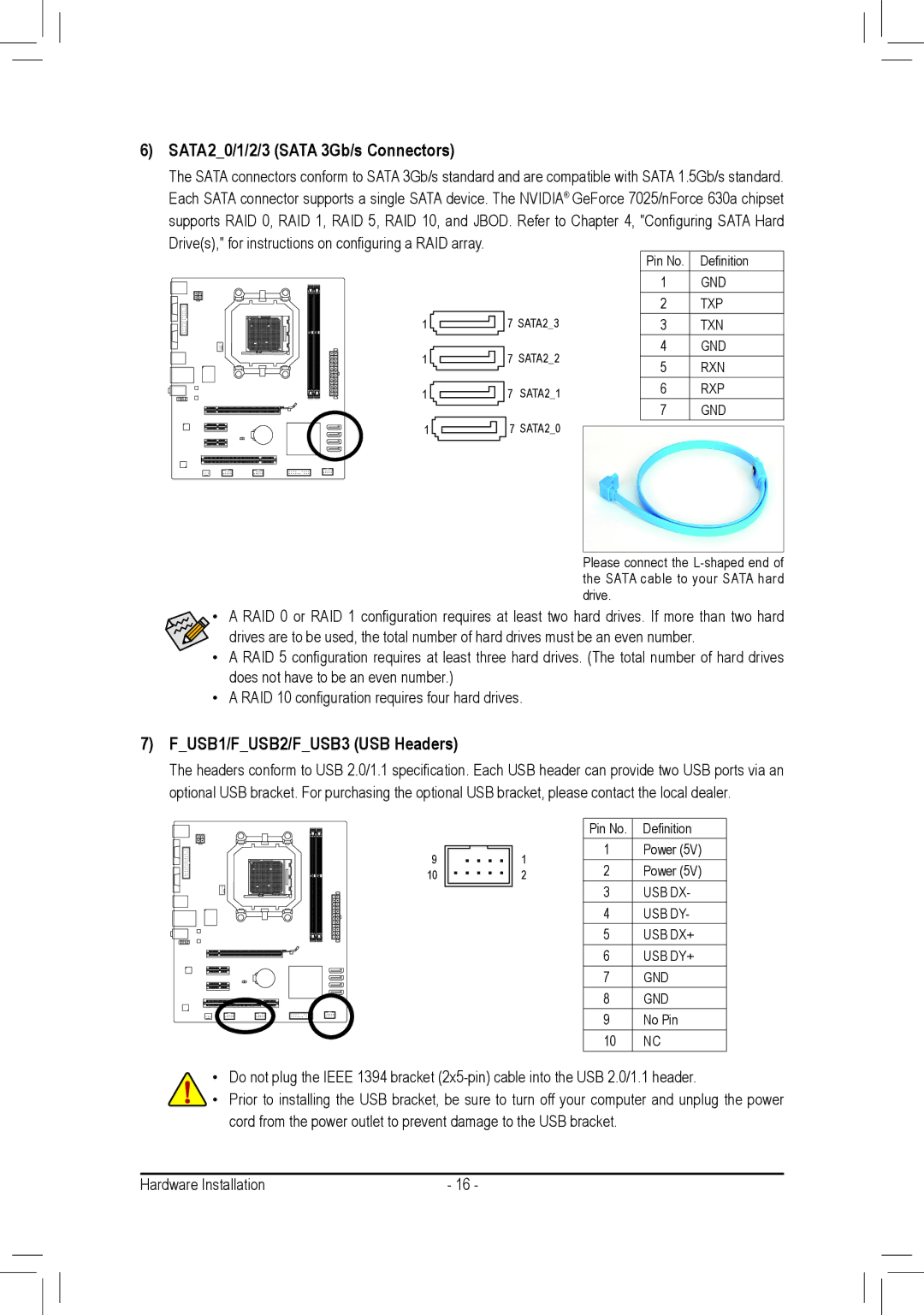
6)SATA2_0/1/2/3 (SATA 3Gb/s Connectors)
The SATA connectors conform to SATA 3Gb/s standard and are compatible with SATA 1.5Gb/s standard. Each SATA connector supports a single SATA device. The NVIDIA® GeForce 7025/nForce 630a chipset supports RAID 0, RAID 1, RAID 5, RAID 10, and JBOD. Refer to Chapter 4, "Configuring SATA Hard
Drive(s)," for instructions on configuring a RAID array.
1 ![]()
1 ![]()
1 ![]()
1 ![]()
7SATA2_3
7SATA2_2
7SATA2_1
7 SATA2_0
Pin No. | Definition |
1 | GND |
2 | TXP |
3 | TXN |
4 | GND |
5 | RXN |
6 | RXP |
7 | GND |
Please connect the
•A RAID 0 or RAID 1 configuration requires at least two hard drives. If more than two hard
drives are to be used, the total number of hard drives must be an even number.
•A RAID 5 configuration requires at least three hard drives. (The total number of hard drives does not have to be an even number.)
•A RAID 10 configuration requires four hard drives.
7)F_USB1/F_USB2/F_USB3 (USB Headers)
The headers conform to USB 2.0/1.1 specification. Each USB header can provide two USB ports via an optional USB bracket. For purchasing the optional USB bracket, please contact the local dealer.
9
10
| Pin No. | Definition | |
1 | 1 | Power (5V) | |
2 | Power (5V) | ||
2 | |||
| 3 | USB DX- | |
| 4 | USB DY- | |
| 5 | USB DX+ | |
| 6 | USB DY+ | |
| 7 | GND | |
| 8 | GND | |
| 9 | No Pin | |
| 10 | NC |
•Do not plug the IEEE 1394 bracket
•Prior to installing the USB bracket, be sure to turn off your computer and unplug the power cord from the power outlet to prevent damage to the USB bracket.
Hardware Installation | - 16 - |