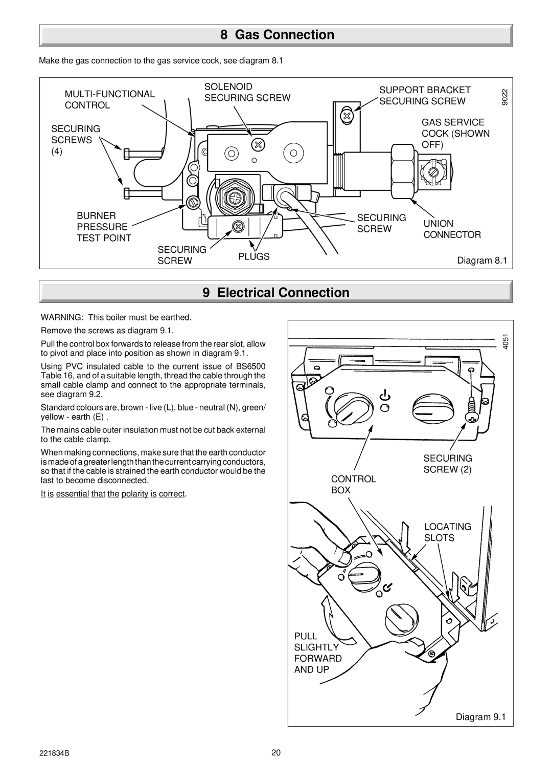
40 specifications
Glowworm Lighting 40 is a popular choice for homeowners seeking energy-efficient heating solutions. This compact, wall-mounted boiler is designed with modern technologies that ensure optimal performance and reliability.One of the standout features of the Glowworm 40 is its impressive efficiency rating. With an energy efficiency of up to 94%, it significantly reduces energy waste, resulting in lower utility bills and a reduced carbon footprint. This is particularly beneficial for environmentally conscious individuals looking to minimize their impact on the planet while maintaining comfort in their homes.
The Glowworm Lighting 40 is equipped with a robust heat exchanger made from high-grade aluminum, which not only enhances heat transfer efficiency but also contributes to the boiler's lightweight design. This feature makes installation easier, allowing for a more flexible placement within the home.
The boiler operates quietly, which is a crucial characteristic for residential areas where noise can be a concern. Its intelligent controls allow users to manage heating temperatures efficiently through programmable timers, ensuring that warmth is delivered only when needed. This not only helps with comfort but also ensures that energy is conserved.
Moreover, the Glowworm Lighting 40 comes with a built-in frost protection feature, which is essential for preventing damage during colder months. This technology ensures that the system remains operational even in extreme conditions, providing peace of mind to homeowners.
Another significant advantage of the Glowworm Lighting 40 is its compatibility with renewable energy technologies. The system can be easily integrated with solar thermal panels, enhancing the overall efficiency of the heating system and aligning with sustainable living principles.
Maintaining the Glowworm Lighting 40 is straightforward, thanks to its accessible design. Regular servicing is uncomplicated, encouraging adherence to maintenance schedules and prolonging the lifespan of the unit. This user-friendly aspect is a crucial consideration for many homeowners.
In summary, the Glowworm Lighting 40 combines efficiency, user-friendly technology, and innovative design. Its high efficiency rating, lightweight structure, quiet operation, and compatibility with renewable energy sources make it a leading contender in the boiler market for those looking for both practicality and environmental consciousness in their heating solutions. Whether upgrading an existing system or installing a new boiler, the Glowworm Lighting 40 delivers on performance and reliability.

