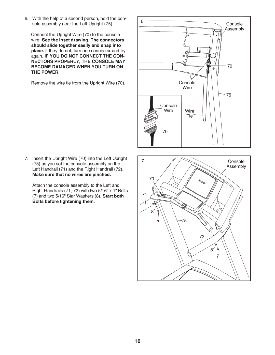
6. With the help of a second person, hold the con- | 6 | Console | |
sole assembly near the Left Upright (75). | |||
Connect the Upright Wire (70) to the console |
| Assembly | |
|
| ||
wire. See the inset drawing. The connectors |
|
| |
should slide together easily and snap into |
|
| |
place. If they do not, turn one connector and try |
|
| |
again. IF YOU DO NOT CONNECT THE CON- |
|
| |
NECTORS PROPERLY, THE CONSOLE MAY |
| 70 | |
BECOME DAMAGED WHEN YOU TURN ON |
| ||
THE POWER. |
|
| |
Remove the wire tie from the Upright Wire (70). |
| Console | |
|
| Wire | |
|
| 75 | |
| Console | Wire | |
| Wire | ||
|
| Tie | |
| 70 |
| |
7. Insert the Upright Wire (70) into the Left Upright | 7 | Console | |
(75) as you set the console assembly on the | |||
| Assembly | ||
Left Handrail (71) and the Right Handrail (72). |
| ||
|
| ||
Make sure that no wires are pinched. | 70 |
| |
Attach the console assembly to the Left and |
| ||
|
| ||
Right Handrails (71, 72) with two 5/16" x 1" Bolts | 71 |
| |
(7) and two 5/16" Star Washers (8). Start both |
| ||
Bolts before tightening them. |
|
| |
| 8 |
| |
| 7 | 75 | |
|
| 72 | |
|
| 8 | |
|
| 7 | |
| 10 |
|