PRODUCT SPECIFICATIONS
SPECIFICATIONS
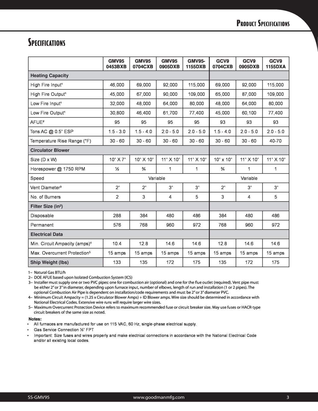
| GMV95 | GMV95 | GMV95 | GMV95- | GCV9 | GCV9 | GCV9 |
| 0453BXB | 0704CXB | 0905DXB | 1155DXB | 0704CXB | 0905DXB | 1155DXA |
Heating Capacity |
|
|
|
|
|
|
|
|
|
|
|
|
|
|
|
High Fire Input¹ | 46,000 | 69,000 | 92,000 | 115,000 | 69,000 | 92,000 | 115,000 |
|
|
|
|
|
|
|
|
High Fire Output¹ | 45,000 | 67,000 | 90,000 | 109,000 | 65,000 | 87,000 | 109,000 |
|
|
|
|
|
|
|
|
Low Fire Input¹ | 32,000 | 48,000 | 64,000 | 80,000 | 48,000 | 64,000 | 80,000 |
|
|
|
|
|
|
|
|
Low Fire Output¹ | 30,800 | 46,400 | 61,700 | 77,400 | 45,000 | 60,100 | 77,400 |
|
|
|
|
|
|
|
|
AFUE² | 95 | 95 | 95 | 95 | 93 | 93 | 93 |
|
|
|
|
|
|
|
|
Tons AC @ 0.5” ESP | 1.5 - 3.0 | 1.5 - 4.0 | 2.0 - 5.0 | 2.0 - 5.0 | 1.5 - 4.0 | 2.0 - 5.0 | 2.0 - 5.0 |
|
|
|
|
|
|
|
|
Temperature Rise Range (°F) | 30 - 60 | 30 - 60 | 30 - 60 | 30 - 60 | 30 - 60 | 30 - 60 | |
|
|
|
|
|
|
|
|
Circulator Blower |
|
|
|
|
|
|
|
|
|
|
|
|
|
|
|
Size (D x W) | 10” X 7” | 10” X 10” | 11” X 10” | 11” X 10” | 10” x 10” | 11” X 10” | 11” X 10” |
|
|
|
|
|
|
|
|
Horespower @ 1750 RPM | ½ | ¾ | 1 | 1 | ¾ | 1 | 1 |
|
|
|
|
|
|
|
|
Speed |
| Variable |
|
| Variable |
| |
|
|
|
|
|
|
|
|
Vent Diameter³ | 2” | 2” | 3” | 3” | 2” | 3” | 3” |
|
|
|
|
|
|
|
|
No. of Burners | 2 | 3 | 4 | 5 | 3 | 4 | 5 |
|
|
|
|
|
|
|
|
Filter Size (in²) |
|
|
|
|
|
|
|
|
|
|
|
|
|
|
|
Disposable | 288 | 384 | 480 | 486 | 384 | 480 | 486 |
|
|
|
|
|
|
|
|
Permanent | 576 | 768 | 960 | 972 | 768 | 960 | 972 |
|
|
|
|
|
|
|
|
Electrical Data |
|
|
|
|
|
|
|
|
|
|
|
|
|
|
|
Min. Circuit Ampacity (amps)4 | 10.4 | 12.8 | 14.6 | 14.6 | 12.8 | 14.6 | 14.6 |
|
|
|
|
|
|
|
|
Max. Overcurrent Protection5 | 15 amps | 15 amps | 15 amps | 15 amps | 15 amps | 15 amps | 15 amps |
|
|
|
|
|
|
|
|
Ship Weight (lbs) | 133 | 135 | 172 | 175 | 135 | 172 | 175 |
|
|
|
|
|
|
|
|
1– Natural Gas BTU/h
2– DOE AFUE based upon Isolated Combustion System (ICS)
3– Installer must supply one or two PVC pipes: one for combustion air (optional) and one for the flue outlet (required). Vent pipe must be either 2” or 3” in diameter, depending upon furnace input, number of elbows, length of run and installation (1 or 2 pipes). The optional Combustion Air Pipe is dependent on installation/code requirements and must be 2” or 3” diameter PVC.
4– Minimum Circuit Ampacity = (1.25 x Circulator Blower Amps) + ID Blower amps. Wire size should be determined in accordance with National Electrical Codes. Extensive wire runs will require larger wire sizes.
5– Maximum Overcurrent Protection Device refers to maximum recommended fuse or circuit breaker size. May use fuses or
Notes:
•All furnaces are manufactured for use on 115 VAC, 60 Hz,
•Gas Service Connection ½” FPT
•Important: Size fuses and wires properly and make electrical connections in accordance with the National Electrical Code and/or all existing local codes.
www.goodmanmfg.com | 3 | |
|
|
|