Return Ductwork
DO NOT TERMINATE THE RETURN DUCTWORK IN AN AREA THAT CAN INTRODUCE TOXIC, OR OBJECTION- ABLE FUMES/ODORS INTO THE DUCTWORK. The return ductwork is to be introduced into the air handler bottom (upflow configuration).
Return Air Filters
Each installation must include a return air filter. This filtering may be performed at the air handler or externally such as a return air filter grille. Air handlers mounted in the downflow orientation, including “B” series, require external filtering. A washable filter is available as an accessory. To ensure opti- mum performance frequent filter cleaning is advised. Refer to Table 1 for the appropriate filter.
ASPF | Filter Number | Qty Required | |
|
|
| |
1830 | FIL | 1 | |
|
|
| |
3137 | FIL | 1 | |
4260 | |||
|
| ||
| Table 1 |
|
Electric Heat
Refer to this manual in combination with the instructions pro- vided with the heat kit for the correct installation procedure.
The air handlers listed in this manual do not have factory installed electric heat. Electric heat is available as an acces- sory. If installing this option, the ONLY heat kits that can be used are the HKR series.
NOTE: The Amana® brand EHK, ECB, EDB, and EDK kits are NOT approved for use with these air handlers.
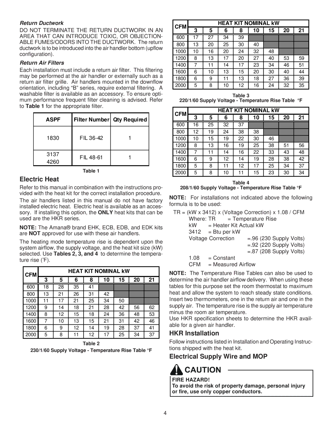
The heating mode temperature rise is dependent upon the system airflow, the supply voltage, and the heat kit size (kW) selected. Use Tables 2, 3, and 4 to determine the tempera- ture rise (ºF).
CFM |
|
| HEAT KIT NOMINAL kW |
|
| ||||
|
|
|
|
|
|
|
|
| |
| 3 | 5 | 6 | 8 | 10 | 15 |
| 20 | 21 |
600 | 18 | 28 | 35 | 41 |
|
|
|
|
|
800 | 13 | 21 | 26 | 31 | 42 |
|
|
|
|
1000 | 11 | 17 | 21 | 25 | 34 | 50 |
|
|
|
1200 | 9 | 14 | 18 | 21 | 28 | 42 |
| 56 | 62 |
1400 | 8 | 12 | 15 | 18 | 24 | 36 |
| 48 | 53 |
1600 | 7 | 10 | 13 | 15 | 21 | 31 |
| 42 | 46 |
1800 | 6 | 9 | 12 | 14 | 19 | 28 |
| 37 | 41 |
2000 | 5 | 8 | 11 | 12 | 17 | 25 |
| 34 | 37 |
Table 2
230/1/60 Supply Voltage - Temperature Rise Table °F
CFM |
|
| HEAT KIT NOMINAL kW |
|
| ||||||
3 | 5 | 6 |
| 8 |
| 10 | 15 |
| 20 | 21 | |
|
|
|
| ||||||||
600 | 17 | 27 | 34 |
| 39 |
|
|
|
|
|
|
800 | 13 | 20 | 25 |
| 30 |
| 40 |
|
|
|
|
1000 | 10 | 16 | 20 |
| 24 |
| 32 | 48 |
|
|
|
1200 | 8 | 13 | 17 |
| 20 |
| 27 | 40 |
| 53 | 59 |
1400 | 7 | 11 | 14 |
| 17 |
| 23 | 34 |
| 46 | 51 |
1600 | 6 | 10 | 13 |
| 15 |
| 20 | 30 |
| 40 | 44 |
1800 | 6 | 9 | 11 |
| 13 |
| 18 | 27 |
| 36 | 39 |
2000 | 5 | 8 | 10 |
| 12 |
| 16 | 24 |
| 32 | 35 |
|
|
|
| Table 3 |
|
|
|
|
| ||
220/1/60 Supply Voltage - Temperature Rise Table °F | |||||||||||
|
|
|
|
|
| ||||||
CFM |
|
| HEAT KIT NOMINAL kW |
|
| ||||||
3 | 5 | 6 |
| 8 |
| 10 | 15 |
| 20 | 21 | |
|
|
|
| ||||||||
600 | 16 | 25 | 32 |
| 37 |
|
|
|
|
|
|
800 | 12 | 19 | 24 |
| 38 |
| 38 |
|
|
|
|
1000 | 10 | 15 | 19 |
| 22 |
| 30 | 46 |
|
|
|
1200 | 8 | 13 | 16 |
| 19 |
| 25 | 38 |
| 51 | 56 |
1400 | 7 | 11 | 14 |
| 16 |
| 22 | 33 |
| 43 | 48 |
1600 | 6 | 9 | 12 |
| 14 |
| 19 | 28 |
| 38 | 42 |
1800 | 5 | 8 | 11 |
| 12 |
| 17 | 25 |
| 34 | 37 |
2000 | 5 | 8 | 10 |
| 11 |
| 15 | 23 |
| 30 | 34 |
Table 4
208/1/60 Supply Voltage - Temperature Rise Table °F
NOTE: For installations not indicated above the following formula is to be used:
TR = (kW x 3412) x (Voltage Correction) x 1.08 / CFM
Where: TR | = Temperature Rise | |
kW | = Heater Kit Actual kW | |
3412 = Btu per kW Voltage Correction
1.08= Constant
CFM = Measured Airflow
NOTE: The Temperature Rise Tables can also be used to determine the air handler airflow delivery. When using these tables for this purpose set the room thermostat to maximum heat and allow the system to reach steady state conditions. Insert two thermometers, one in the return air and one in the supply air. The temperature rise is the supply air temperature minus the room air temperature.
Use HKR specification sheets to determine the HKR avail- able for a given air handler.
HKR Installation
Follow instructions listed in Installation and Operating Instruc- tions shipped with the heat kit.
Electrical Supply Wire and MOP
FIRE HAZARD!
To avoid the risk of property damage, personal injury or fire, use only copper conductors.
4