Standby Generator Sets
Specifications
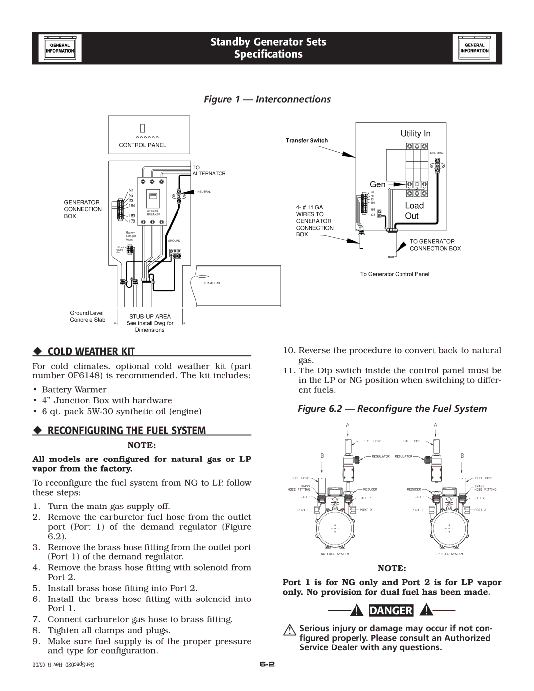
Figure 1 — Interconnections
CONTROL PANEL
Utility In
Transfer Switch
NEUTRAL
GENERATOR CONNECTION BOX
| TO |
| ALTERNATOR |
N1 | NEUTRAL |
N2 |
|
23 |
|
194 |
|
| CIRCUIT |
183 | BREAKER |
| |
178 |
|
Battery |
|
Charger |
|
Input | GROUND |
| |
120 Volt + |
|
Neutral |
|
Grd |
|
| Gen |
|
| N1 |
|
| N2 |
|
4- # 14 GA | 23 | Load |
186 | ||
| 194 |
|
WIRES TO | 178 | Out |
|
|
GENERATOR
CONNECTION BOX
TO GENERATOR
CONNECTION BOX
To Generator Control Panel
FRAME RAIL
Ground Level
Concrete Slab
See Install Dwg for
Dimensions
COLD WEATHER KIT
For cold climates, optional cold weather kit (part number 0F6148) is recommended. The kit includes:
•Battery Warmer
•4” Junction Box with hardware
•6 qt. pack
| CIRCUIT BREAKER SIZE | ||
KW | VOLTS | / AMPS | LUG SIZE |
45 | 240 1 Ø | 200 | #6 to 300 mcm |
45 | 208 3 Ø | 175 | #6 to 300 mcm |
45 | 480 3 Ø | 80 | #6 to 300 mcm |
|
|
|
|
10.Reverse the procedure to convert back to natural gas.
11.The Dip switch inside the control panel must be in the LP or NG position when switching to differ- ent fuels.
Figure 6.2 — Reconfigure the Fuel System
RECONFIGURING THE FUEL SYSTEM
NOTE:
All models are configured for natural gas or LP vapor from the factory.
To reconfigure the fuel system from NG to LP, follow these steps:
1.Turn the main gas supply off.
2.Remove the carburetor fuel hose from the outlet port (Port 1) of the demand regulator (Figure 6.2).
3.Remove the brass hose fitting from the outlet port (Port 1) of the demand regulator.
4.Remove the brass hose fitting with solenoid from Port 2.
5.Install brass hose fitting into Port 2.
6.Install the brass hose fitting with solenoid into Port 1.
7.Connect carburetor gas hose to brass fitting.
8.Tighten all clamps and plugs.
9.Make sure fuel supply is of the proper pressure and type for configuration.
NOTE:
Port 1 is for NG only and Port 2 is for LP vapor only. No provision for dual fuel has been made.
![]()
![]() DANGER
DANGER
Serious injury or damage may occur if not con- figured properly. Please consult an Authorized Service Dealer with any questions.
05/06 B .Rev GenSpec020