5.Align the quill keyway with the entry hole of the quill lock lever (see Figure 13), then install the lever into the tailstock so that the end of it mates with the quill keyway.
Note: Make sure the
Quill
Keyway
Quill
Lock Lever
Figure 13. Quill lock lever.
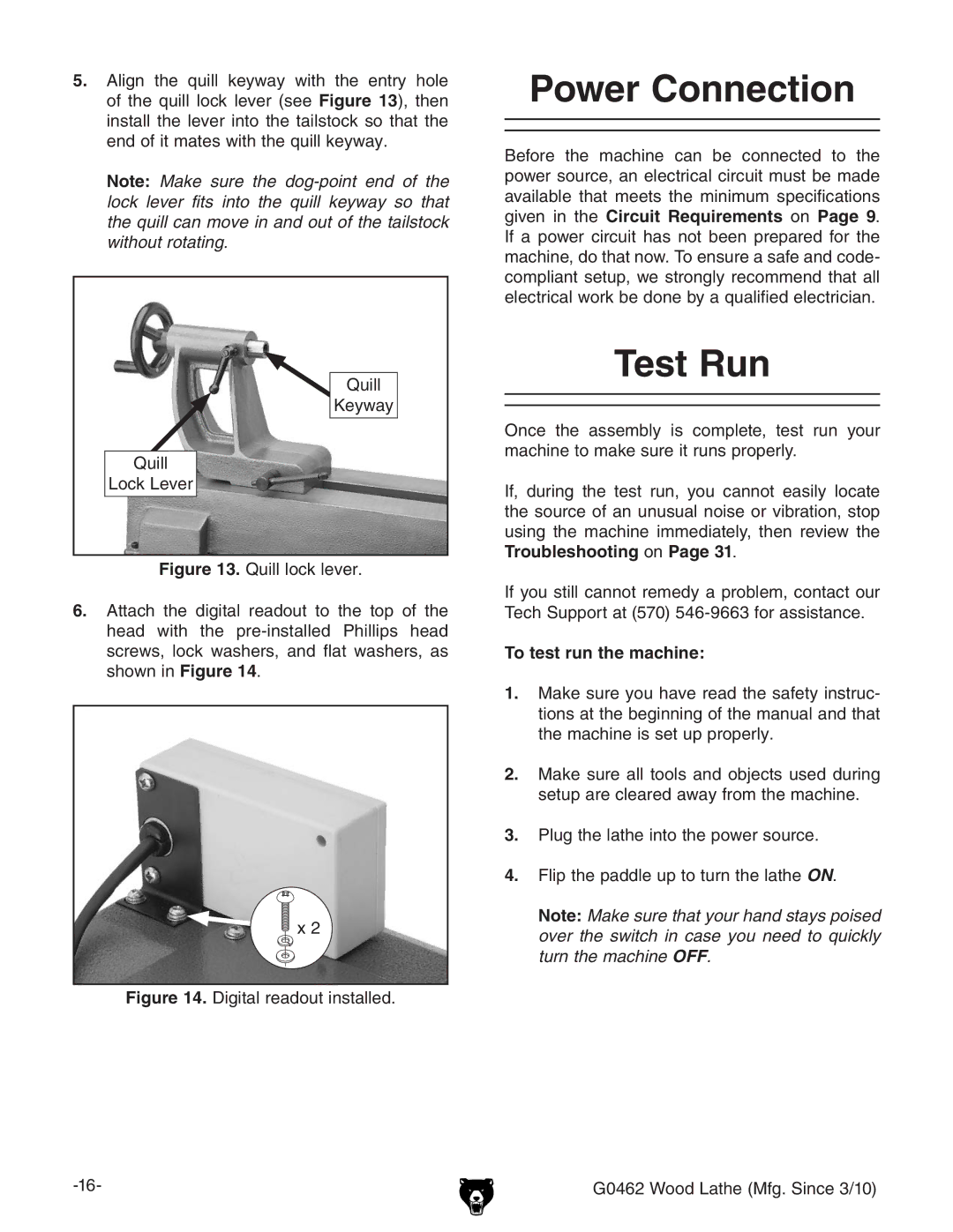
6.Attach the digital readout to the top of the head with the pre-installed Phillips head screws, lock washers, and flat washers, as shown in Figure 14.
![]() x 2
x 2
Figure 14. Digital readout installed.
Power Connection
Before the machine can be connected to the power source, an electrical circuit must be made available that meets the minimum specifications given in the Circuit Requirements on Page 9. If a power circuit has not been prepared for the machine, do that now. To ensure a safe and code- compliant setup, we strongly recommend that all electrical work be done by a qualified electrician.
Test Run
Once the assembly is complete, test run your machine to make sure it runs properly.
If, during the test run, you cannot easily locate the source of an unusual noise or vibration, stop using the machine immediately, then review the Troubleshooting on Page 31.
If you still cannot remedy a problem, contact our Tech Support at (570)
To test run the machine:
1.Make sure you have read the safety instruc- tions at the beginning of the manual and that the machine is set up properly.
2.Make sure all tools and objects used during setup are cleared away from the machine.
3.Plug the lathe into the power source.
4.Flip the paddle up to turn the lathe ON.
Note: Make sure that your hand stays poised over the switch in case you need to quickly turn the machine OFF.
G0462 Wood Lathe (Mfg. Since 3/10)