Gearbox Levers
NOTICE
NEVER move levers while the lathe is run- ning, and NEVER force any lever when shift- ing. If the lever will not engage, rotate the chuck by hand while keeping light pressure on the lever. As the chuck rotates it aligns the gears and the lever will engage.
The two levers (Figure 27) at the bottom of the headstock change the feed rate, or the number of threads cut
Use the feed rate chart shown in Figure 28 to position the quick change gearbox levers.
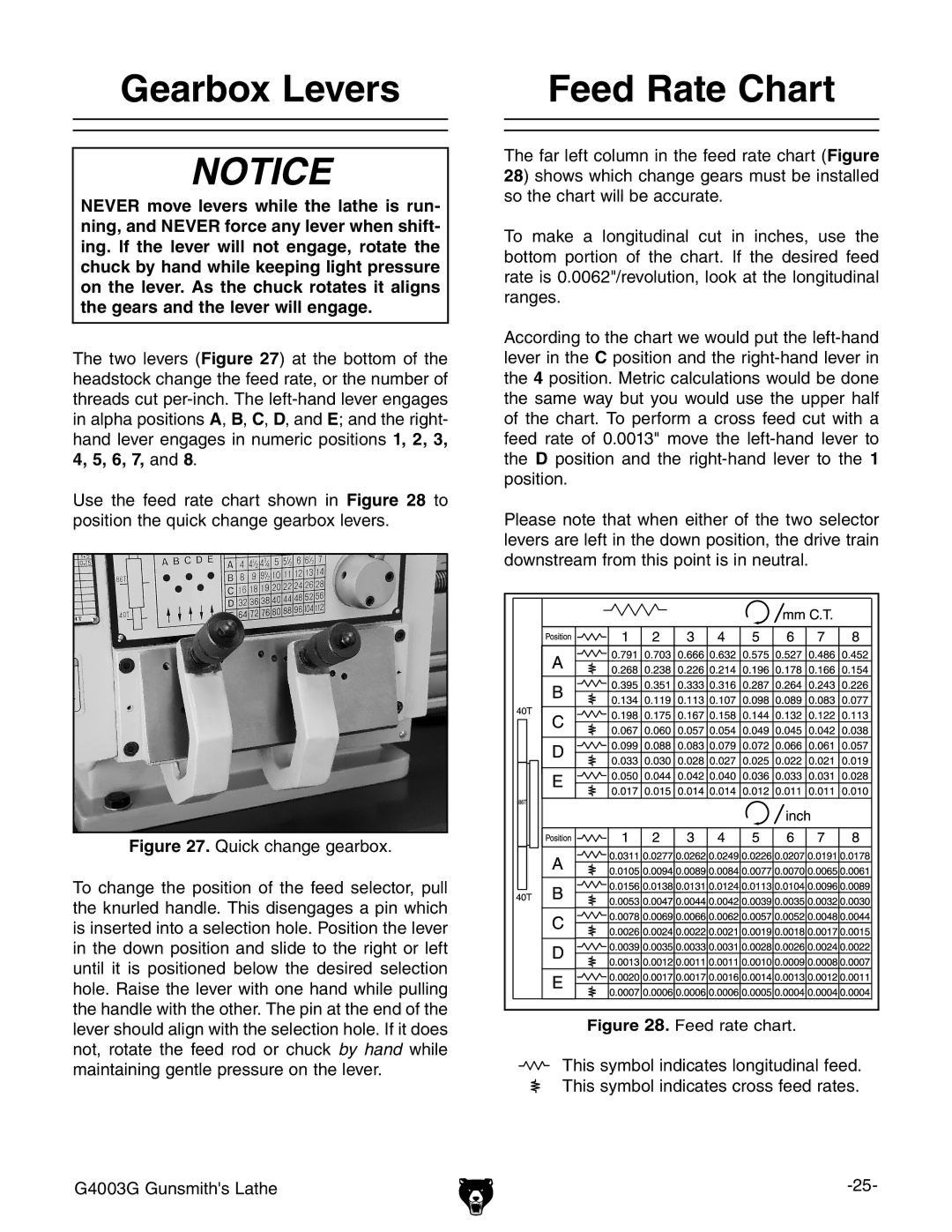
Figure 27. Quick change gearbox.
To change the position of the feed selector, pull the knurled handle. This disengages a pin which is inserted into a selection hole. Position the lever in the down position and slide to the right or left until it is positioned below the desired selection hole. Raise the lever with one hand while pulling the handle with the other. The pin at the end of the lever should align with the selection hole. If it does not, rotate the feed rod or chuck by hand while maintaining gentle pressure on the lever.
G4003G Gunsmith's Lathe
Feed Rate Chart
The far left column in the feed rate chart (Figure 28) shows which change gears must be installed so the chart will be accurate.
To make a longitudinal cut in inches, use the bottom portion of the chart. If the desired feed rate is 0.0062"/revolution, look at the longitudinal ranges.
According to the chart we would put the
Please note that when either of the two selector levers are left in the down position, the drive train downstream from this point is in neutral.
Figure 28. Feed rate chart.
This symbol indicates longitudinal feed. This symbol indicates cross feed rates.