5.Loosen the 17mm
���
���
������
���� | ��� |
������������ | ��� |
������� | ������ |
����
�����������
�������
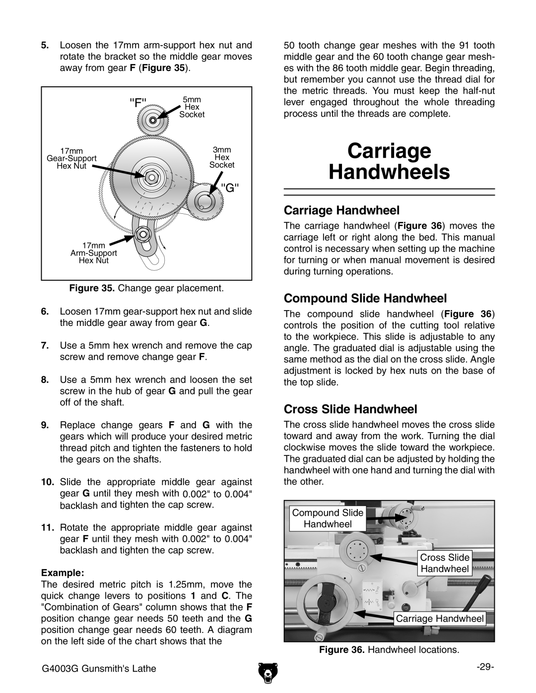
Figure 35. Change gear placement.
6.Loosen 17mm gear-support hex nut and slide the middle gear away from gear G.
7.Use a 5mm hex wrench and remove the cap screw and remove change gear F.
8.Use a 5mm hex wrench and loosen the set screw in the hub of gear G and pull the gear off of the shaft.
9.Replace change gears F and G with the gears which will produce your desired metric thread pitch and tighten the fasteners to hold the gears on the shafts.
10.Slide the appropriate middle gear against gear G until they mesh with 0.002" to 0.004" backlash and tighten the cap screw.
11.Rotate the appropriate middle gear against gear F until they mesh with 0.002" to 0.004" backlash and tighten the cap screw.
Example:
The desired metric pitch is 1.25mm, move the quick change levers to positions 1 and C. The "Combination of Gears" column shows that the F position change gear needs 50 teeth and the G position change gear needs 60 teeth. A diagram on the left side of the chart shows that the
G4003G Gunsmith's Lathe
50 tooth change gear meshes with the 91 tooth middle gear and the 60 tooth change gear mesh- es with the 86 tooth middle gear. Begin threading, but remember you cannot use the thread dial for the metric threads. You must keep the
Carriage
Handwheels
Carriage Handwheel
The carriage handwheel (Figure 36) moves the carriage left or right along the bed. This manual control is necessary when setting up the machine for turning or when manual movement is desired during turning operations.
Compound Slide Handwheel
The compound slide handwheel (Figure 36) controls the position of the cutting tool relative to the workpiece. This slide is adjustable to any angle. The graduated dial is adjustable using the same method as the dial on the cross slide. Angle adjustment is locked by hex nuts on the base of the top slide.
Cross Slide Handwheel
The cross slide handwheel moves the cross slide toward and away from the work. Turning the dial clockwise moves the slide toward the workpiece. The graduated dial can be adjusted by holding the handwheel with one hand and turning the dial with the other.
Compound Slide |
Handwheel |
Cross Slide |
Handwheel |
Carriage Handwheel |