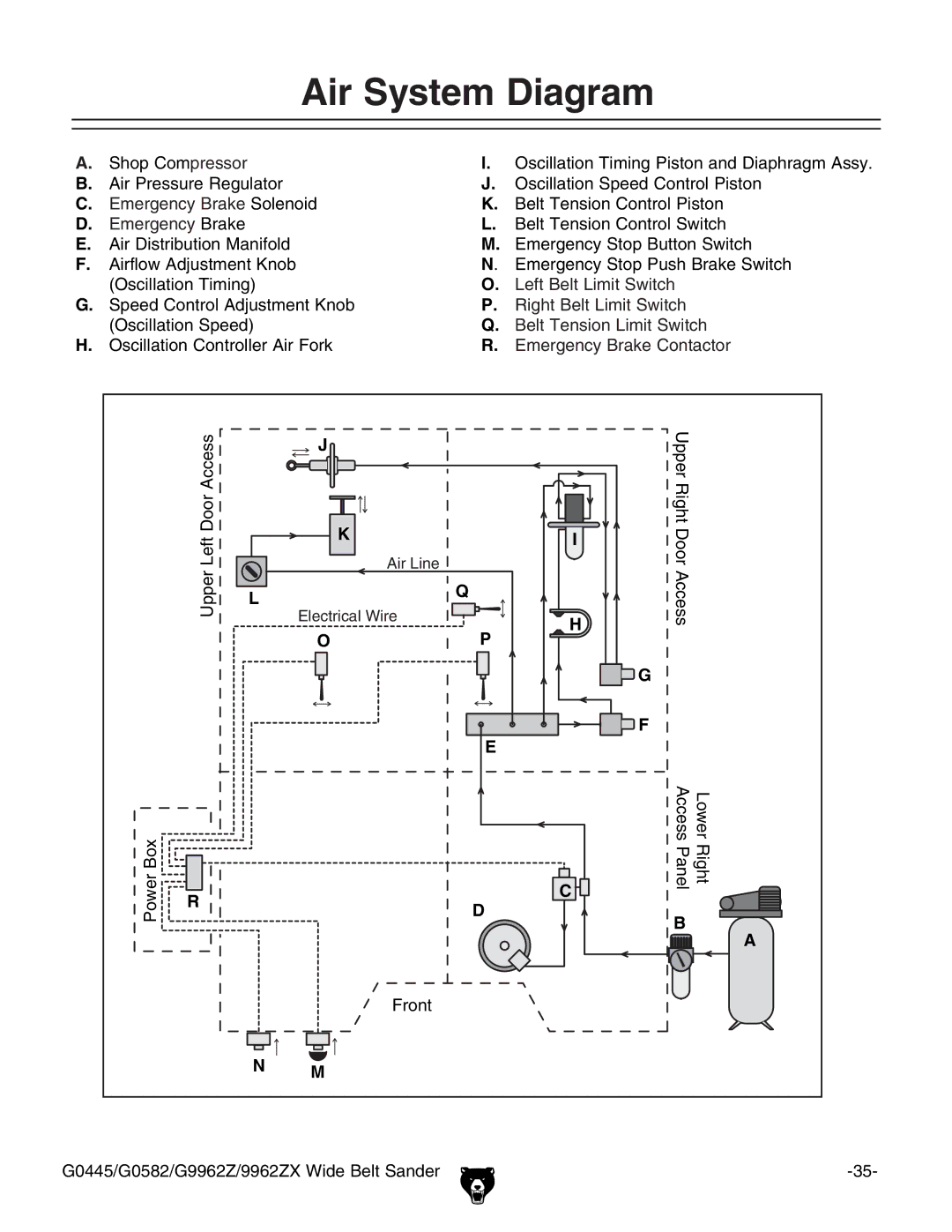
Air System Diagram
A. | Shop Compressor | I. | Oscillation Timing Piston and Diaphragm Assy. |
B. | Air Pressure Regulator | J. | Oscillation Speed Control Piston |
C. | Emergency Brake Solenoid | K. | Belt Tension Control Piston |
D. | Emergency Brake | L. | Belt Tension Control Switch |
E. | Air Distribution Manifold | M. | Emergency Stop Button Switch |
F. | Airflow Adjustment Knob | N. | Emergency Stop Push Brake Switch |
| (Oscillation Timing) | O. | Left Belt Limit Switch |
G. | Speed Control Adjustment Knob | P. | Right Belt Limit Switch |
| (Oscillation Speed) | Q. | Belt Tension Limit Switch |
H. | Oscillation Controller Air Fork | R. | Emergency Brake Contactor |
Power Box
Upper Left Door Access
R
J![]()
| K | |
| �������� | |
L | Q | |
��������������� | ||
|
OP
E
D
Front
NM
I
![]() H
H
![]() G
G
![]()
![]()
![]() F
F
C ![]()
Upper Right Door Access
Access | RightLower |
Panel |
|
B![]()
![]() A
A
G0445/G0582/G9962Z/9962ZX Wide Belt Sander |
