Exhaust Venting


DRAFTHOOD


SCREW


TAB LEG


EXHAUST


FAN


SLOT


REVERSE


FLOW OF


GASES


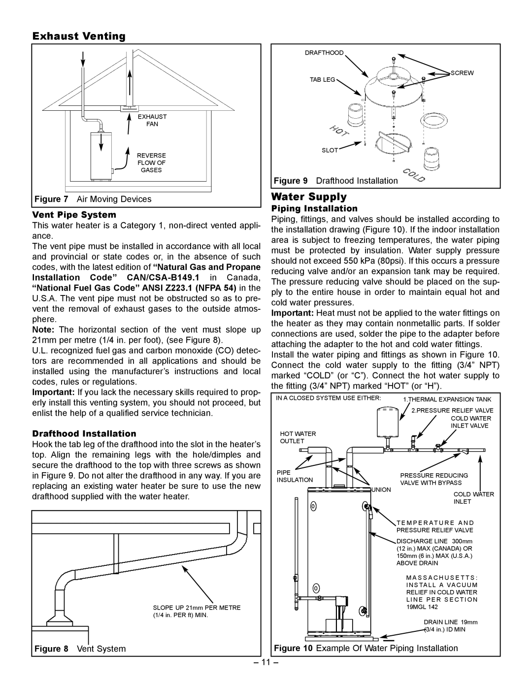
Figure 9


Drafthood Installation


Figure 7 Air Moving Devices


Water Supply


Piping Installation


Vent Pipe System


Piping, fittings, and valves should be installed according to

This water heater is a Category 1, non-direct vented appli-


the installation drawing (Figure 10). If the indoor installation

ance.


area is subject to freezing temperatures, the water piping

The vent pipe must be installed in accordance with all local


must be

protected

by insulation. Water supply pressure

and provincial or state codes or, in the absence of such


should not exceed 550 kPa (80psi). If this occurs a pressure

codes, with the latest edition of “Natural Gas and Propane


reducing valve and/or an expansion tank may be required.

Installation

Code”

CAN/CSA-B149.1

in

Canada,


The pressure reducing valve should be placed on the sup-

“National Fuel Gas Code” ANSI Z223.1 (NFPA 54) in the


ply to the entire house in order to maintain equal hot and

U.S.A. The vent pipe must not be obstructed so as to pre-


cold water pressures.


vent the removal of exhaust gases to the outside atmos-


Important: Heat must not be applied to the water fittings on

phere.


the heater as they may contain nonmetallic parts. If solder

Note: The

horizontal

section of the vent

must

slope up


connections are used, solder the pipe to the adapter before

21mm per metre (1/4 in. per foot), (see Figure 8).


attaching the adapter to the hot and cold water fittings.

U.L. recognized fuel gas and carbon monoxide (CO) detec-


Install the water piping and fittings as shown in Figure 10.

tors are recommended in all applications and should be


Connect

the cold

water supply

to the fitting (3/4” NPT)

installed using


the manufacturer’s instructions

and local


marked “COLD” (or “C”). Connect the hot water supply to

codes, rules or regulations.


the fitting (3/4” NPT) marked “HOT” (or “H”).

Important: If you lack the necessary skills required to prop-


erly install this venting system, you should not proceed, but


IN A CLOSED SYSTEM USE EITHER:


1.THERMAL EXPANSION TANK


enlist the help of a qualified service technician.


2.PRESSURE RELIEF VALVE


COLD WATER


Drafthood Installation


INLET VALVE


HOT WATER


Hook the tab leg of the drafthood into the slot in the heater’s


OUTLET


top. Align the remaining legs with the hole/dimples and


secure the drafthood to the top with three screws as shown


in Figure 9. Do not alter the drafthood in any way. If you are


PIPE


PRESSURE REDUCING


INSULATION


replacing an existing water heater be sure to use the new


VALVE WITH BYPASS


UNION


drafthood supplied with the water heater.


COLD WATER


INLET


T E M P E R AT U R E A N D


PRESSURE RELIEF VALVE


DISCHARGE LINE 300mm


(12 in.) MAX (CANADA) OR


150mm (6 in.) MAX (U.S.A.)


ABOVE DRAIN


M A S S A C H U S E T T S :


I N S TA L L A VA C U U M


RELIEF IN COLD WATER


L I N E P E R S E C T I O N


19MGL 142


SLOPE UP 21mm PER METRE


(1/4 in. PER ft) MIN.


DRAIN LINE 19mm


(3/4 in.) ID MIN


Figure 8

Vent System


Figure 10 Example Of Water Piping Installation


11


Page 11
Image 11
GSW 72090 manual Exhaust Venting, Water Supply

72090 specifications

The GSW 72090 is a remarkable addition to the world of modern heating solutions, designed to provide efficient and effective space heating. It epitomizes advanced technology, reliability, and user-centric design, making it an ideal choice for homes and commercial spaces alike.

One of the main features of the GSW 72090 is its impressive heating capacity. Engineered to deliver optimal warmth, it can efficiently heat larger areas, ensuring that spaces remain comfortable even during the coldest months. The unit’s high-grade alloy construction enhances durability and helps maintain consistent performance over time.

A vital technology integrated into the GSW 72090 is its modulating control system. This system intelligently adjusts the temperature output based on the current heating demand, optimizing energy usage and contributing to lower utility bills. This efficiency not only benefits the consumer but also has a positive impact on the environment by reducing greenhouse gas emissions.

The GSW 72090 also boasts a sleek and modern aesthetic, making it an attractive addition to any space. Its design allows for easy installation and maintenance, ensuring that users can focus on comfort without worrying about the complexities of upkeep. The unit operates quietly, providing a peaceful environment without the disruptive noises often associated with traditional heating systems.

Incorporating safety features is another key characteristic of the GSW 72090. It includes overheat protection, which automatically turns the unit off if it detects excessive temperatures, ensuring a safe environment for occupants. Additionally, the product is constructed with materials that are resistant to corrosion and wear, enhancing longevity.

As an environmentally conscious option, the GSW 72090 is designed to comply with stringent energy efficiency regulations. Its performance not only meets but often exceeds the required standards, making it a smart choice for those looking to reduce their carbon footprint.

Overall, the GSW 72090 stands out due to its combination of advanced technologies, user-friendly features, aesthetic appeal, and commitment to safety and efficiency. Its multi-faceted capabilities make it a prime option for anyone seeking reliable and effective heating solutions in their home or business.