|
|
| Advanced Troubleshooting |
|
|
|
|
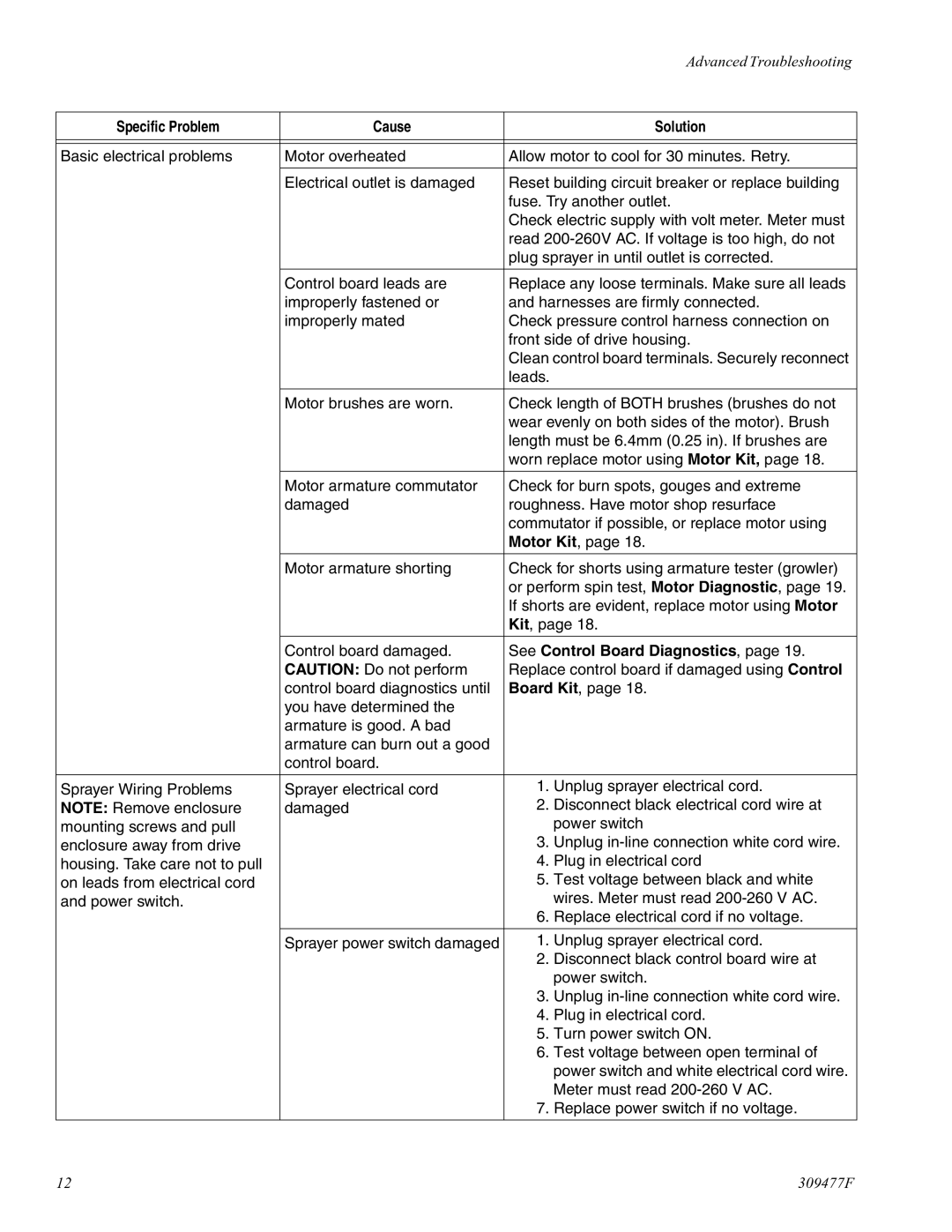
Specific Problem | Cause |
| Solution |
|
|
| |
|
|
| |
Basic electrical problems | Motor overheated | Allow motor to cool for 30 minutes. Retry. | |
|
|
| |
| Electrical outlet is damaged | Reset building circuit breaker or replace building | |
|
| fuse. Try another outlet. | |
|
| Check electric supply with volt meter. Meter must | |
|
| read | |
|
| plug sprayer in until outlet is corrected. | |
|
|
| |
| Control board leads are | Replace any loose terminals. Make sure all leads | |
| improperly fastened or | and harnesses are firmly connected. | |
| improperly mated | Check pressure control harness connection on | |
|
| front side of drive housing. | |
|
| Clean control board terminals. Securely reconnect | |
|
| leads. |
|
|
|
| |
| Motor brushes are worn. | Check length of BOTH brushes (brushes do not | |
|
| wear evenly on both sides of the motor). Brush | |
|
| length must be 6.4mm (0.25 in). If brushes are | |
|
| worn replace motor using Motor Kit, page 18. | |
|
|
| |
| Motor armature commutator | Check for burn spots, gouges and extreme | |
| damaged | roughness. Have motor shop resurface | |
|
| commutator if possible, or replace motor using | |
|
| Motor Kit, page 18. | |
|
|
| |
| Motor armature shorting | Check for shorts using armature tester (growler) | |
|
| or perform spin test, Motor Diagnostic, page 19. | |
|
| If shorts are evident, replace motor using Motor | |
|
| Kit, page 18. | |
|
|
| |
| Control board damaged. | See Control Board Diagnostics, page 19. | |
| CAUTION: Do not perform | Replace control board if damaged using Control | |
| control board diagnostics until | Board Kit, page 18. | |
| you have determined the |
|
|
| armature is good. A bad |
|
|
| armature can burn out a good |
|
|
| control board. |
|
|
|
|
|
|
Sprayer Wiring Problems | Sprayer electrical cord | 1. | Unplug sprayer electrical cord. |
NOTE: Remove enclosure | damaged | 2. | Disconnect black electrical cord wire at |
mounting screws and pull |
|
| power switch |
enclosure away from drive |
| 3. | Unplug |
housing. Take care not to pull |
| 4. | Plug in electrical cord |
on leads from electrical cord |
| 5. | Test voltage between black and white |
and power switch. |
|
| wires. Meter must read |
|
| 6. | Replace electrical cord if no voltage. |
|
|
|
|
| Sprayer power switch damaged | 1. | Unplug sprayer electrical cord. |
|
| 2. | Disconnect black control board wire at |
|
|
| power switch. |
|
| 3. | Unplug |
|
| 4. | Plug in electrical cord. |
|
| 5. | Turn power switch ON. |
|
| 6. | Test voltage between open terminal of |
|
|
| power switch and white electrical cord wire. |
|
|
| Meter must read |
|
| 7. | Replace power switch if no voltage. |
|
|
|
|
12 | 309477F |