III.Unpacking the System
In addition to the assembled unit, these components are packed loosely or separately: suction assembly, hose set, gun, instruction manuals. These are the manuals you should receive:
Husky 307 pump | |
Air spray gun | |
Fluid regulator | |
Fluid heater | |
Fluid filter |
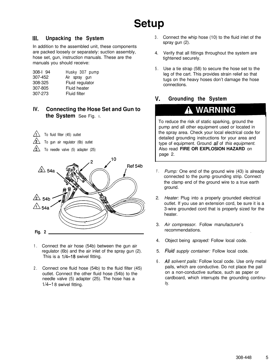
IV. Connecting the Hose Set and Gun to the System See Fig. I.
A1 To fluid filter (45) outlet
A2 To gun air regulator (6b) outlet
A3 To needle valve (5) adapter (25)
Fig. 2
1 . Connect the air hose (54b) between the gun air regulator (6b) and the air inlet of the spray gun (2). This is a
2 . Connect one fluid hose (54b) to the fluid filter (45) outlet. Connect the other fluid hose (54b) to the needle valve (5) adapter (25). The hose has a
3 . Connect the whip hose (10) to the fluid inlet of the spray gun (2).
4.Verify that all fittings throughout the system are tightened securely.
5 . Use a tie strap (58) to secure the hose set to the leg of the cart. This provides strain relief so that tugs on the heavy hoses don’t damage the hose connections.
v. Grounding the System
To reduce the risk of static sparking, ground the pump and all other equipment used or located in the spray area. Check your local electrical code for detailed grounding instructions for your area and type of equipment. Ground all of this equipment. Also read FIRE OR EXPLOSION HAZARD on page 2.
1 . Pump: One end of the ground wire (43) is already connected to the pump grounding strip. Connect the clamp end of the ground wire to a true earth ground.
2.Heater: Plug into a properly grounded electrical outlet. If you use an extension cord, be sure it is a
3.Air compressor. Follow manufacturer’s
recommendations..
4.Object being sprayed: Follow local code.
5.Fluid supply container: Follow local code.
6 . All solvent pails: Follow local code. Use only metal pails, which are conductive. Do not place the pail on a
