Outdoor unit
![]() Wiring work
Wiring work
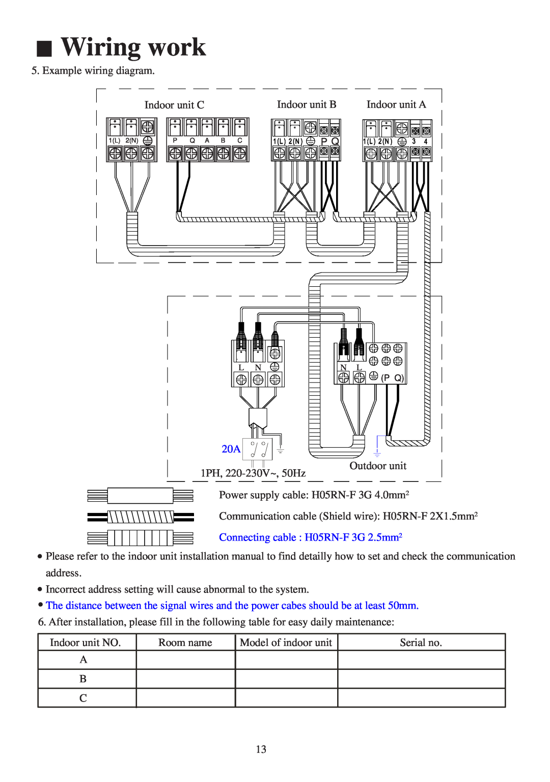
5. Example wiring diagram.
Indoor unit C
1(L) | 2(N) | P | Q | A | B | C |
Indoor unit B | Indoor unit A |
P Q |
L | N | N | L |
|
|
| (P Q) |
20A
1PH,
Power supply cable:
Communication cable (Shield wire):
Connecting cable :
![]() Please refer to the indoor unit installation manual to find detailly how to set and check the communication address.
Please refer to the indoor unit installation manual to find detailly how to set and check the communication address.
![]() Incorrect address setting will cause abnormal to the system.
Incorrect address setting will cause abnormal to the system.
![]() The distance between the signal wires and the power cabes should be at least 50mm. 6. After installation, please fill in the following table for easy daily maintenance:
The distance between the signal wires and the power cabes should be at least 50mm. 6. After installation, please fill in the following table for easy daily maintenance:
Indoor unit NO. | Room name | Model of indoor unit | Serial no. |
A |
|
|
|
|
|
|
|
B |
|
|
|
|
|
|
|
C |
|
|
|
|
|
|
|
13