BACK LID
(20)
FIGURE E
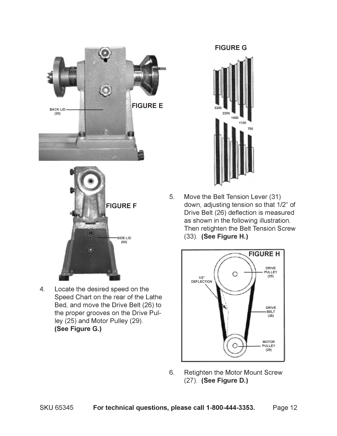
FIGURE G
3200
2200
1600
1100
750
FIGURE F
SIDE LID
(63)
5.Move the Belt Tension Lever (31) down, adjusting tension so that 1/2” of
Drive Belt (26) deflection is measured as shown in the following illustration. Then retighten the Belt Tension Screw (33). (See Figure H.)
FIGURE H
4.Locate the desired speed on the Speed Chart on the rear of the Lathe Bed, and move the Drive Belt (26) to the proper grooves on the Drive Pul- ley (25) and Motor Pulley (29).
(See Figure G.)
DRIVE
PULLEY
1/2”(25)
DEFLECTION
DRIVE
BELT
(26)
MOTOR ![]() PULLEY
PULLEY
(29)
6. Retighten the Motor Mount Screw
| (27). (See Figure D.) |
|
SKU 65345 | For technical questions, please call | Page 12 |