7.Replace the Back Lid (20) and Side Lid (63). (See Figures E and F.)
FIGURE I
Recommended Turning Speeds
Work Diameter | Speeds (RPM) |
In Inches |
|
0~2” | 2200~3200 |
2”~3” | 1600~2200 |
3”~4” | 1100~1600 |
4”~5” | 750~1100 |
6”+ | 750 |
Note: The above speeds can vary with different types of wood and the skill of the operator. Sanding: Use the fastest speed possible with- out burning the wood.
Polishing and Finishing: Typically, polishing and finishing can be done at faster speeds than turning.
To Adjust The Tailstock:
1.Loosen the Release Lever (7) and move the Tailstock (5) to the desired position. Then retighten the Release Lever. NOTE: If the Release Lever will not release or lock the Tailstock (either too tight or too loose), tighten or loosen the Hex Nut (44) located on the underside of the Tailstock in small increments as needed to achieve the proper clamping pressure.
(See Figure J and Assy. Diagram.)
TAILSTOCK |
| RELEASE | |
| LEVER | ||
(5) |
| ||
(7) | |||
| |||
FIGURE J
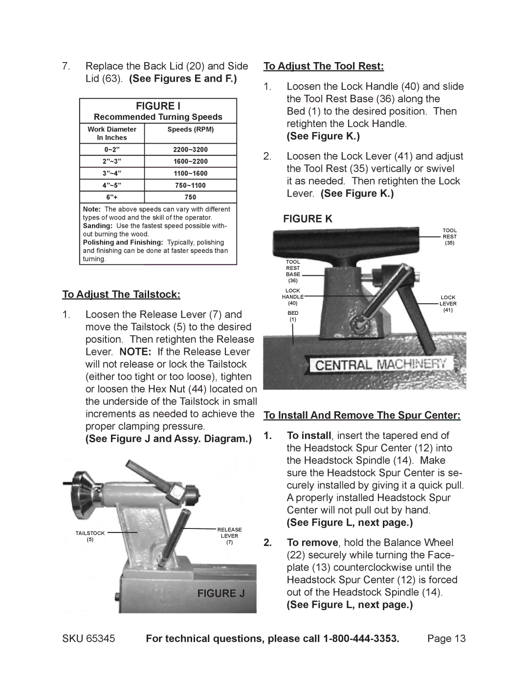
To Adjust The Tool Rest:
1.Loosen the Lock Handle (40) and slide the Tool Rest Base (36) along the Bed (1) to the desired position. Then retighten the Lock Handle.
(See Figure K.)
2.Loosen the Lock Lever (41) and adjust the Tool Rest (35) vertically or swivel it as needed. Then retighten the Lock Lever. (See Figure K.)
FIGURE K
|
|
|
|
|
|
|
| TOOL |
|
|
|
|
|
|
|
| REST |
|
|
|
|
|
|
|
| |
|
| (35) | ||||||
TOOL |
|
|
|
|
|
|
| |
REST |
|
|
|
|
|
|
| |
BASE |
|
|
|
|
|
|
|
|
|
|
|
|
|
|
|
| |
(36) |
|
|
|
|
|
|
|
|
LOCK |
|
|
|
|
|
|
| |
HANDLE |
|
|
|
|
|
| LOCK | |
|
| |||||||
(40) |
|
|
|
|
|
| LEVER | |
|
|
|
|
| ||||
BED | (41) | |||||||
|
|
|
|
|
|
| ||
(1) |
|
|
|
|
|
|
|
|
To Install And Remove The Spur Center:
1.To install, insert the tapered end of the Headstock Spur Center (12) into the Headstock Spindle (14). Make sure the Headstock Spur Center is se- curely installed by giving it a quick pull. A properly installed Headstock Spur Center will not pull out by hand.
(See Figure L, next page.)
2.To remove, hold the Balance Wheel (22) securely while turning the Face- plate (13) counterclockwise until the Headstock Spur Center (12) is forced out of the Headstock Spindle (14).
(See Figure L, next page.)
SKU 65345 | For technical questions, please call | Page 13 |