6.Use a wood mallet to drive the Head- stock Spur Center (12) into the center of the workpiece at least 1/4” deep.
(See Figure Q.)
FIGURE Q
HEADSTOCK
SPUR
CENTER
(12)
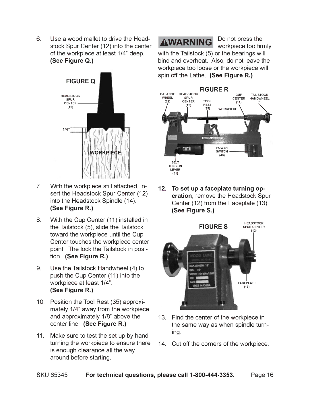
Do not press the workpiece too firmly
with the Tailstock (5) or the bearings will bind and overheat. Also, do not leave the workpiece too loose or the workpiece will spin off the Lathe. (See Figure R.)
FIGURE R
BALANCE | HEADSTOCK |
|
|
| CUP | TAILSTOCK | |
WHEEL | SPUR | TOOL |
| CENTER | HANDWHEEL | ||
(22) | CENTER | (11) | (5) | ||||
| (12) | REST |
|
|
| ||
|
|
| (35) | WORKPIECE |
| ||
|
|
|
| ||||
|
|
|
|
|
|
|
|
|
|
|
|
|
|
|
|
1/4”
WORKPIECE
POWER SWITCH (46)
BELT
TENSION
LEVER
(31)
7.With the workpiece still attached, in- sert the Headstock Spur Center (12) into the Headstock Spindle (14).
(See Figure R.)
8.With the Cup Center (11) installed in the Tailstock (5), slide the Tailstock toward the workpiece until the Cup Center touches the workpiece center point. The lock the Tailstock in posi- tion. (See Figure R.)
9.Use the Tailstock Handwheel (4) to push the Cup Center (11) into the workpiece at least 1/4”.
(See Figure R.)
10.Position the Tool Rest (35) approxi- mately 1/4” away from the workpiece and approximately 1/8” above the center line. (See Figure R.)
11.Make sure to test the set up by hand turning the workpiece to ensure there is enough clearance all the way around before starting.
12.To set up a faceplate turning op- eration, remove the Headstock Spur Center (12) from the Faceplate (13).
(See Figure S.)
HEADSTOCK
FIGURE S SPUR CENTER (12)
FACEPLATE
(13)
13.Find the center of the workpiece in the same way as when spindle turn- ing.
14.Cut off the corners of the workpiece.
SKU 65345 | For technical questions, please call | Page 16 |