3.With assistance, turn the assembled Base right side up. (See Figure F.)
4.With assistance, move the assembled Base to the floor surface where the Router will be used. NOTE: Make sure the floor surface is dry, flat, level, and sturdy enough to support the weight of the Router, workpieces, and any additional tools and equipment. Use the four Support Legs 2 (9A) as a tem- plate to mark four places where mounting holes will be drilled in the floor surface. Then, temporarily set the assembled Base aside. (See Figure F.)
5.Drill four mounting holes of appropriate size into the floor surface. Then move the assembled Base back to its original position, making sure to align the mount- ing holes in the Support Legs 2 (9A) with the mounting holes drilled into the floor.
6.Secure the four Support Legs 2 (9A) to the floor surface, using four bolts, lock washers, and nuts (not included). NOTE: It is recommended to use expansion anchor bolts for concrete and lag bolts for wooden floors.
7.Slightly loosen the Screws (3A) on the Support Legs 2 (9A) of the assembled Base. Adjust the height of each Support Leg 2 (9A) until the Base is level. Then, retighten the Screws. (See Figure F.)
To Assemble The Mid-Section:
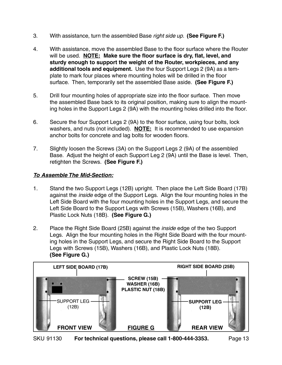
1.Stand the two Support Legs (12B) upright. Then place the Left Side Board (17B) against the inside edge of the Support Legs. Align the four mounting holes in the Left Side Board with the four mounting holes in the Support Legs, and secure the Left Side Board to the Support Legs with Screws (15B), Washers (16B), and Plastic Lock Nuts (18B). (See Figure G.)
2.Place the Right Side Board (25B) against the inside edge of the two Support Legs. Align the four mounting holes in the Right Side Board with the four mount- ing holes in the Support Legs, and secure the Right Side Board to the Support Legs with Screws (15B), Washers (16B), and Plastic Lock Nuts (18B).
(See Figure G.)
LEFT SIDE BOARD (17B) |
|
|
|
| RIGHT SIDE BOARD (25B) | |||||||
|
|
|
|
|
| SCREW (15B) |
|
|
|
| ||
|
|
|
|
|
|
| ||||||
|
|
|
|
|
|
|
|
| ||||
|
|
|
|
|
|
|
| |||||
|
|
|
|
|
| WASHER (16B) | ||||||
|
|
|
|
| PLASTIC NUT (18B) | |||||||
| SUPPORT LEG |
|
|
|
|
|
|
| SUPPORT LEG |
| ||
|
|
| ||||||||||
|
|
|
| |||||||||
|
|
|
| |||||||||
| (12B) |
|
|
|
|
| (12B) | |||||
FRONT VIEW | FIGURE G | REAR VIEW |
SKU 91130 | For technical questions, please call | Page 13 |