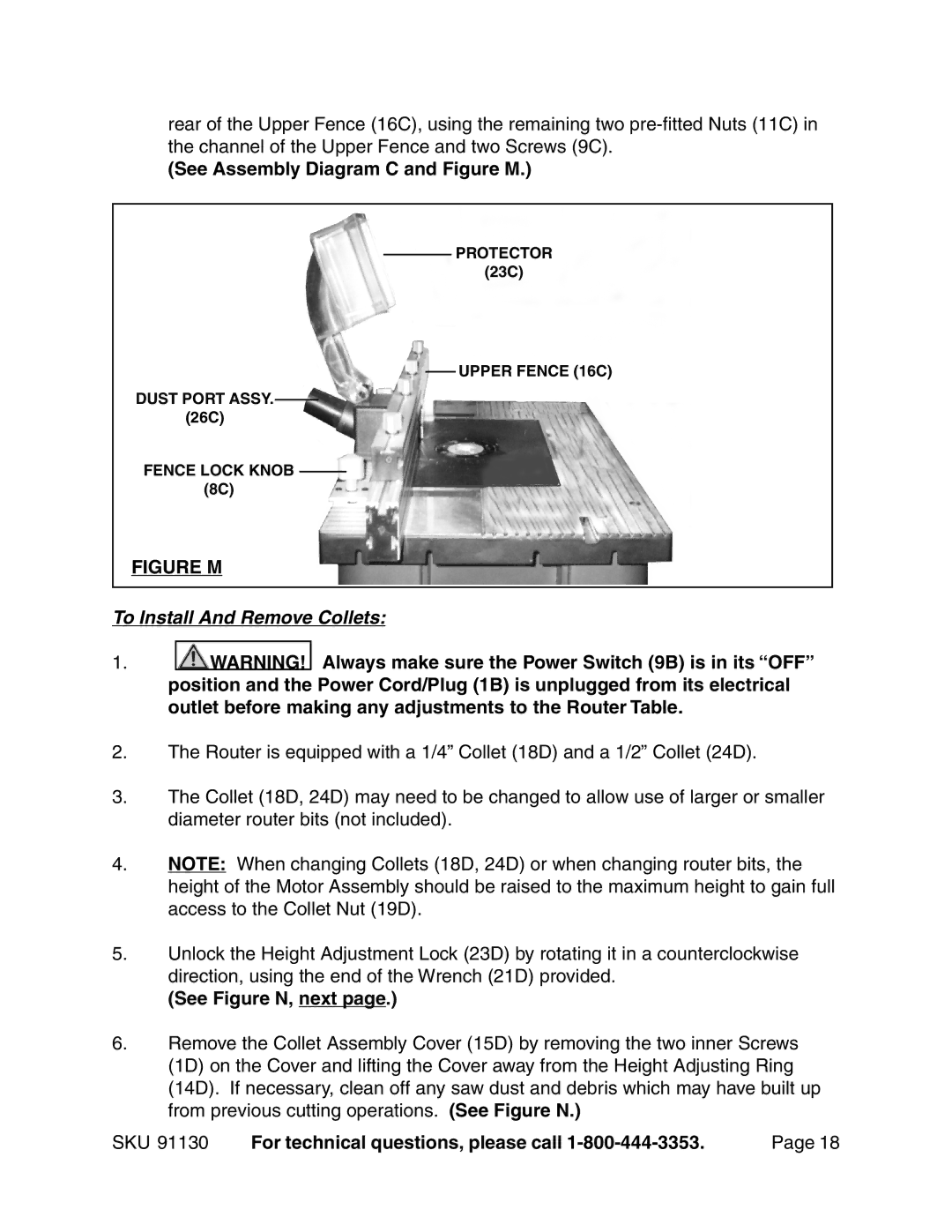
rear of the Upper Fence (16C), using the remaining two
(See Assembly Diagram C and Figure M.)
PROTECTOR
(23C)
UPPER FENCE (16C)
DUST PORT ASSY.
(26C)
FENCE LOCK KNOB
(8C)
FIGURE M
To Install And Remove Collets:
1.![]()
![]() WARNING! Always make sure the Power Switch (9B) is in its “OFF” position and the Power Cord/Plug (1B) is unplugged from its electrical outlet before making any adjustments to the Router Table.
WARNING! Always make sure the Power Switch (9B) is in its “OFF” position and the Power Cord/Plug (1B) is unplugged from its electrical outlet before making any adjustments to the Router Table.
2.The Router is equipped with a 1/4” Collet (18D) and a 1/2” Collet (24D).
3.The Collet (18D, 24D) may need to be changed to allow use of larger or smaller diameter router bits (not included).
4.NOTE: When changing Collets (18D, 24D) or when changing router bits, the height of the Motor Assembly should be raised to the maximum height to gain full access to the Collet Nut (19D).
5.Unlock the Height Adjustment Lock (23D) by rotating it in a counterclockwise direction, using the end of the Wrench (21D) provided.
(See Figure N, next page.)
6.Remove the Collet Assembly Cover (15D) by removing the two inner Screws (1D) on the Cover and lifting the Cover away from the Height Adjusting Ring (14D). If necessary, clean off any saw dust and debris which may have built up from previous cutting operations. (See Figure N.)
SKU 91130 | For technical questions, please call | Page 18 |