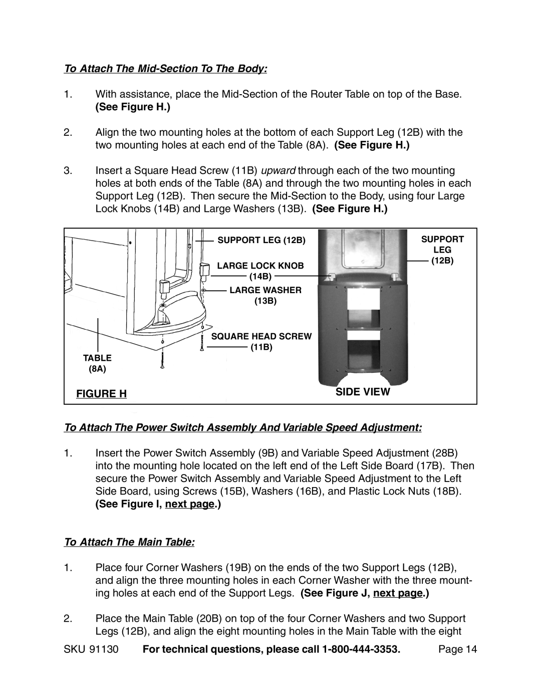
To Attach The Mid-Section To The Body:
1.With assistance, place the
(See Figure H.)
2.Align the two mounting holes at the bottom of each Support Leg (12B) with the two mounting holes at each end of the Table (8A). (See Figure H.)
3.Insert a Square Head Screw (11B) upward through each of the two mounting holes at both ends of the Table (8A) and through the two mounting holes in each Support Leg (12B). Then secure the
|
|
|
|
|
| SUPPORT LEG (12B) |
| SUPPORT | |||||
|
|
|
|
|
| ||||||||
|
|
|
|
|
|
|
|
|
|
|
|
| LEG |
|
|
|
|
|
| LARGE LOCK KNOB |
|
| (12B) | ||||
|
|
|
|
|
|
|
| ||||||
|
|
|
|
|
|
|
|
| |||||
|
|
|
|
|
|
|
|
| (14B) |
|
|
|
|
|
|
|
|
|
|
|
|
|
|
|
|
| |
|
|
|
|
|
|
| LARGE WASHER |
|
|
| |||
|
|
|
|
|
|
|
|
|
| ||||
|
|
|
|
|
|
|
|
| (13B) |
|
|
| |
|
|
|
|
| SQUARE HEAD SCREW |
|
|
| |||||
|
|
|
|
|
|
|
| ||||||
|
|
|
|
|
|
|
|
| (11B) |
|
|
| |
|
|
|
|
|
|
|
|
|
|
|
| ||
TABLE |
|
|
| ||||||||||
(8A) |
|
|
| ||||||||||
FIGURE H | SIDE VIEW | ||||||||||||
|
|
|
|
|
|
|
|
|
|
|
|
|
|
To Attach The Power Switch Assembly And Variable Speed Adjustment:
1.Insert the Power Switch Assembly (9B) and Variable Speed Adjustment (28B) into the mounting hole located on the left end of the Left Side Board (17B). Then secure the Power Switch Assembly and Variable Speed Adjustment to the Left Side Board, using Screws (15B), Washers (16B), and Plastic Lock Nuts (18B).
(See Figure I, next page.)
To Attach The Main Table:
1.Place four Corner Washers (19B) on the ends of the two Support Legs (12B), and align the three mounting holes in each Corner Washer with the three mount- ing holes at each end of the Support Legs. (See Figure J, next page.)
2.Place the Main Table (20B) on top of the four Corner Washers and two Support Legs (12B), and align the eight mounting holes in the Main Table with the eight
SKU 91130 | For technical questions, please call | Page 14 |