|
|
| SCREW (15B) | ||||
|
|
| WASHER (16B) | ||||
LEFT SIDE BOARD (17B) |
| PLASTIC LOCK NUT (18B) | |||||
|
|
|
|
|
| ||
|
| POWER |
|
|
|
| |
|
|
|
|
|
| ||
|
| ||||||
|
| SWITCH | |||||
|
| (9B) |
|
|
| ||
|
|
|
|
|
|
| |
|
|
| |||||
|
|
|
|
|
|
|
|
|
|
|
|
|
|
|
|
|
|
|
|
|
| VARIABLE | |
|
|
|
|
|
| SPEED | |
|
|
|
|
| ADJUSTMENT | ||
|
|
|
|
|
| (28B) | |
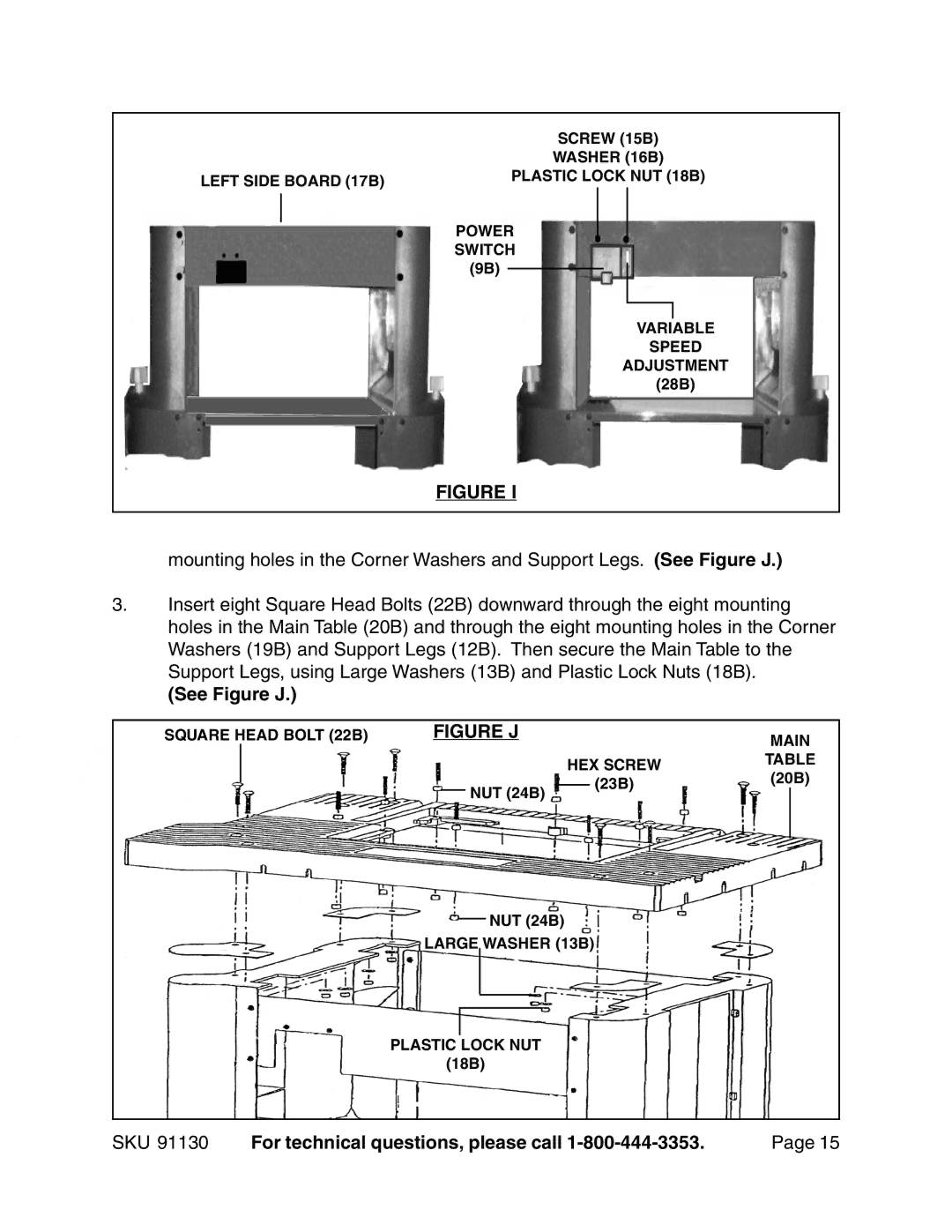
FIGURE I
mounting holes in the Corner Washers and Support Legs. (See Figure J.)
3.Insert eight Square Head Bolts (22B) downward through the eight mounting holes in the Main Table (20B) and through the eight mounting holes in the Corner Washers (19B) and Support Legs (12B). Then secure the Main Table to the Support Legs, using Large Washers (13B) and Plastic Lock Nuts (18B).
(See Figure J.)
SQUARE HEAD BOLT (22B) | FIGURE J |
|
| MAIN | ||||
|
|
|
|
|
|
| ||
|
|
|
|
| HEX SCREW | TABLE | ||
|
|
|
|
| (20B) | |||
|
|
|
| NUT (24B) |
| (23B) | ||
|
|
|
|
|
|
| ||
|
|
|
|
|
|
|
| |
|
|
|
|
|
|
|
|
|
NUT (24B)
LARGE WASHER (13B)
PLASTIC LOCK NUT
(18B)
SKU 91130 | For technical questions, please call | Page 15 |