ASSEMBLY AND OPERATING INSTRUCTIONS (continued)
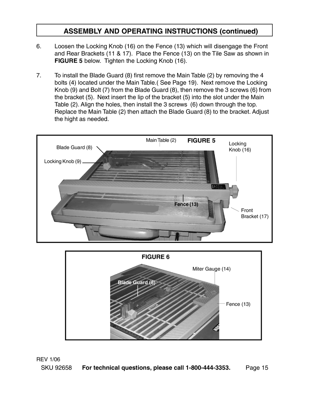
6.Loosen the Locking Knob (16) on the Fence (13) which will disengage the Front and Rear Brackets (11 & 17). Place the Fence (13) on the Tile Saw as shown in FIGURE 5 below. Tighten the Locking Knob (16).
7.To install the Blade Guard (8) first remove the Main Table (2) by removing the 4 bolts (4) located under the Main Table.( See Page 19). Next remove the Locking Knob (9) and Bolt (7) from the Blade Guard (8), then remove the 3 screws (6) from the bracket (5). Next insert the lip of the bracket (5) into the slot under the Main Table (2). Align the holes, then install the 3 screws (6) down through the top. Replace the Main Table (2) then attach the Blade Guard (8) to the bracket. Adjust the hight as needed.
Main |
| Table (2) | FIGURE 5 | Locking | |
| |||||
Blade Guard (8) |
|
|
| Knob (16) | |
|
|
|
| ||
Locking Knob (9) |
|
|
| ||
|
|
| |||
|
|
|
|
|
|
Fence (13)
![]() Front
Front
Bracket (17)
FIGURE 6
Miter Gauge (14)
Blade Guard (8)
Fence (13)
REV 1/06
SKU 92658 For technical questions, please call | Page 15 |
