(44)up under the rail and over the end of the Bolt (59), then 2) secure it using a Nut
(61).Use two Hold Down Connectors for each Corner Stud.
3.Remove the Nuts (61) you used in step 1 to assemble the Side Floor Plates (18a, 18b), install a Hold Down Connector (44) over the end of each Bolt (59), and rein- stall all Nuts (61).
4.Place three Short Bolts (59) and Nuts (61) into the holes on the Top Doorway Beam
(14).Do not tighten them yet. While making sure that the profiles of the parts are
oriented as shown to the right, slide the slot on the Door Rail (28) 14 over the heads of the three bolts on the Top Doorway Beam.
Center the Door Rail on the Doorway Beam then tighten the | 28 | |
Nuts. | ||
|
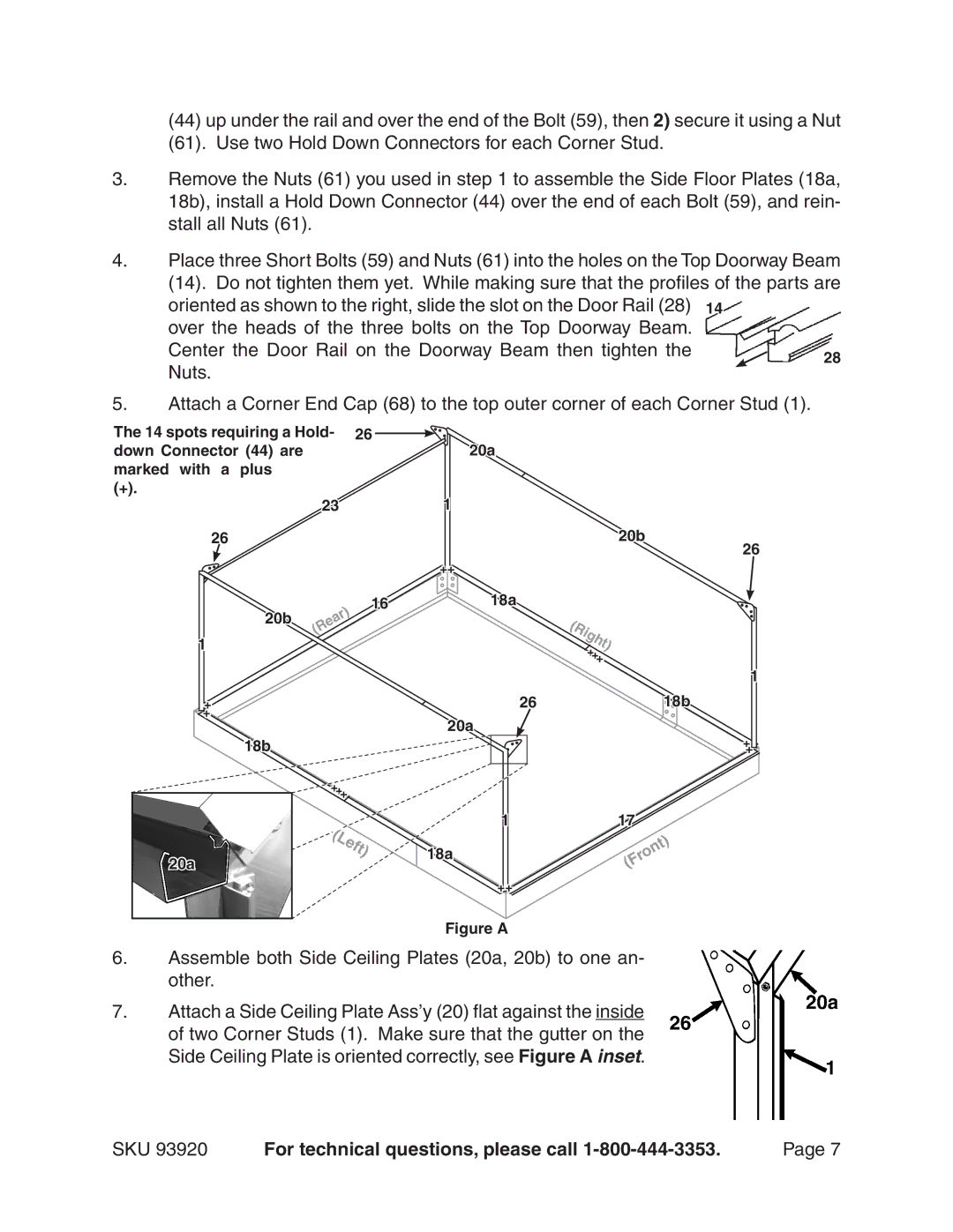
5.Attach a Corner End Cap (68) to the top outer corner of each Corner Stud (1).
The 14 spots requiring a Hold- 26 ![]() down Connector (44) are
down Connector (44) are
marked with a plus
(+).
23
26
20a
1
20b
++
26
1
20b
1618a
(Rear)
(Right) +++
1
+ |
| 26 | 18b |
+ |
| 20a |
|
|
|
| |
| 18b |
|
|
| +++ |
|
|
| eft) | 1 | 17 |
|
|
| |
| (L |
| Front) |
20a |
| 18a | |
| ( | ||
|
| ||
|
|
| |
|
| ++ |
|
Figure A
6.Assemble both Side Ceiling Plates (20a, 20b) to one an- other.
7.Attach a Side Ceiling Plate Ass’y (20) flat against the inside of two Corner Studs (1). Make sure that the gutter on the
Side Ceiling Plate is oriented correctly, see Figure A inset.
+
+
SKU 93920 | For technical questions, please call | Page |
