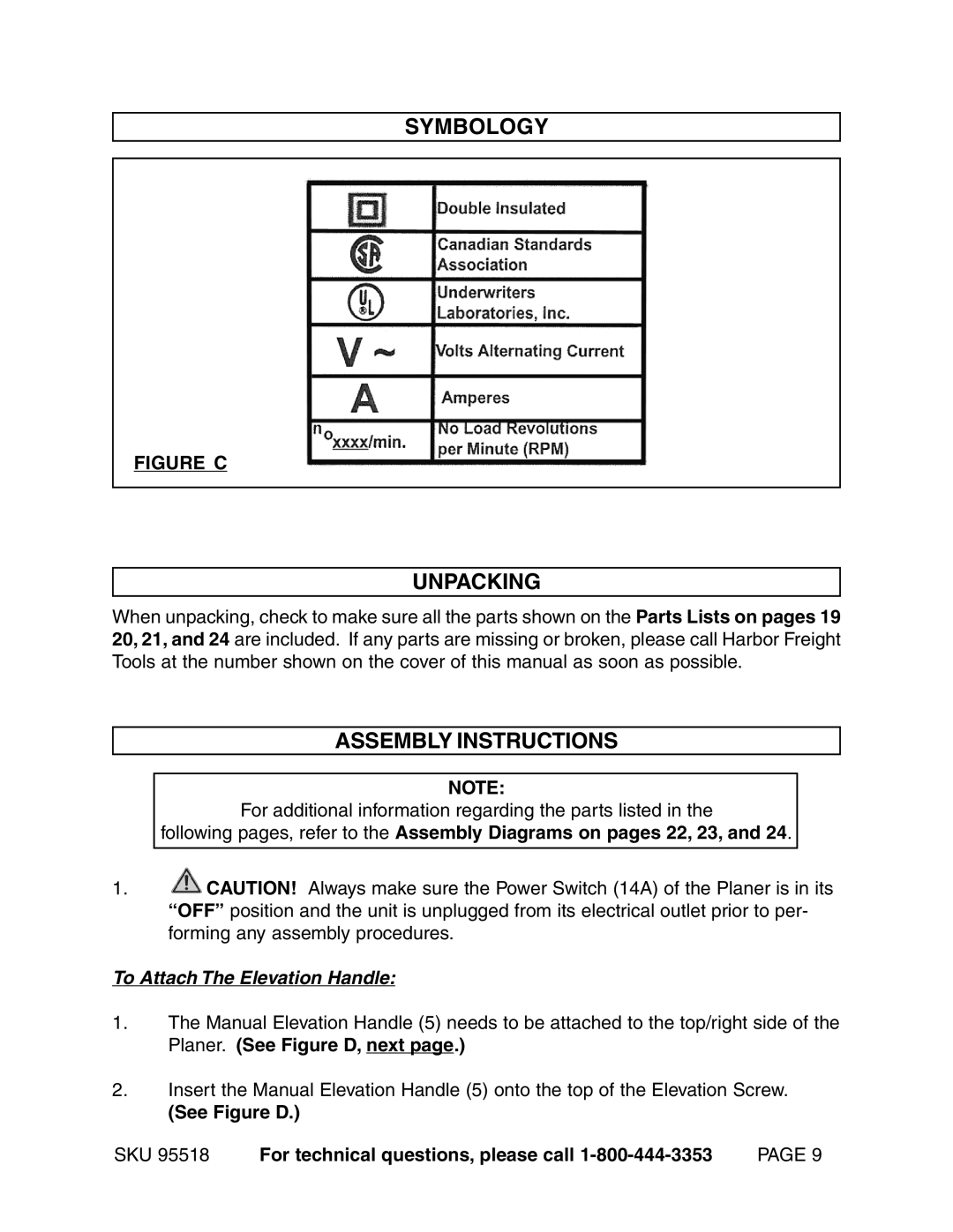
SYMBOLOGY
FIGURE C
UNPACKING
When unpacking, check to make sure all the parts shown on the Parts Lists on pages 19 20, 21, and 24 are included. If any parts are missing or broken, please call Harbor Freight Tools at the number shown on the cover of this manual as soon as possible.
ASSEMBLY INSTRUCTIONS
NOTE:
For additional information regarding the parts listed in the
following pages, refer to the Assembly Diagrams on pages 22, 23, and 24.
1.![]() CAUTION! Always make sure the Power Switch (14A) of the Planer is in its “OFF” position and the unit is unplugged from its electrical outlet prior to per- forming any assembly procedures.
CAUTION! Always make sure the Power Switch (14A) of the Planer is in its “OFF” position and the unit is unplugged from its electrical outlet prior to per- forming any assembly procedures.
To Attach The Elevation Handle:
1.The Manual Elevation Handle (5) needs to be attached to the top/right side of the Planer. (See Figure D, next page.)
2.Insert the Manual Elevation Handle (5) onto the top of the Elevation Screw.
(See Figure D.)
SKU 95518 For technical questions, please call
