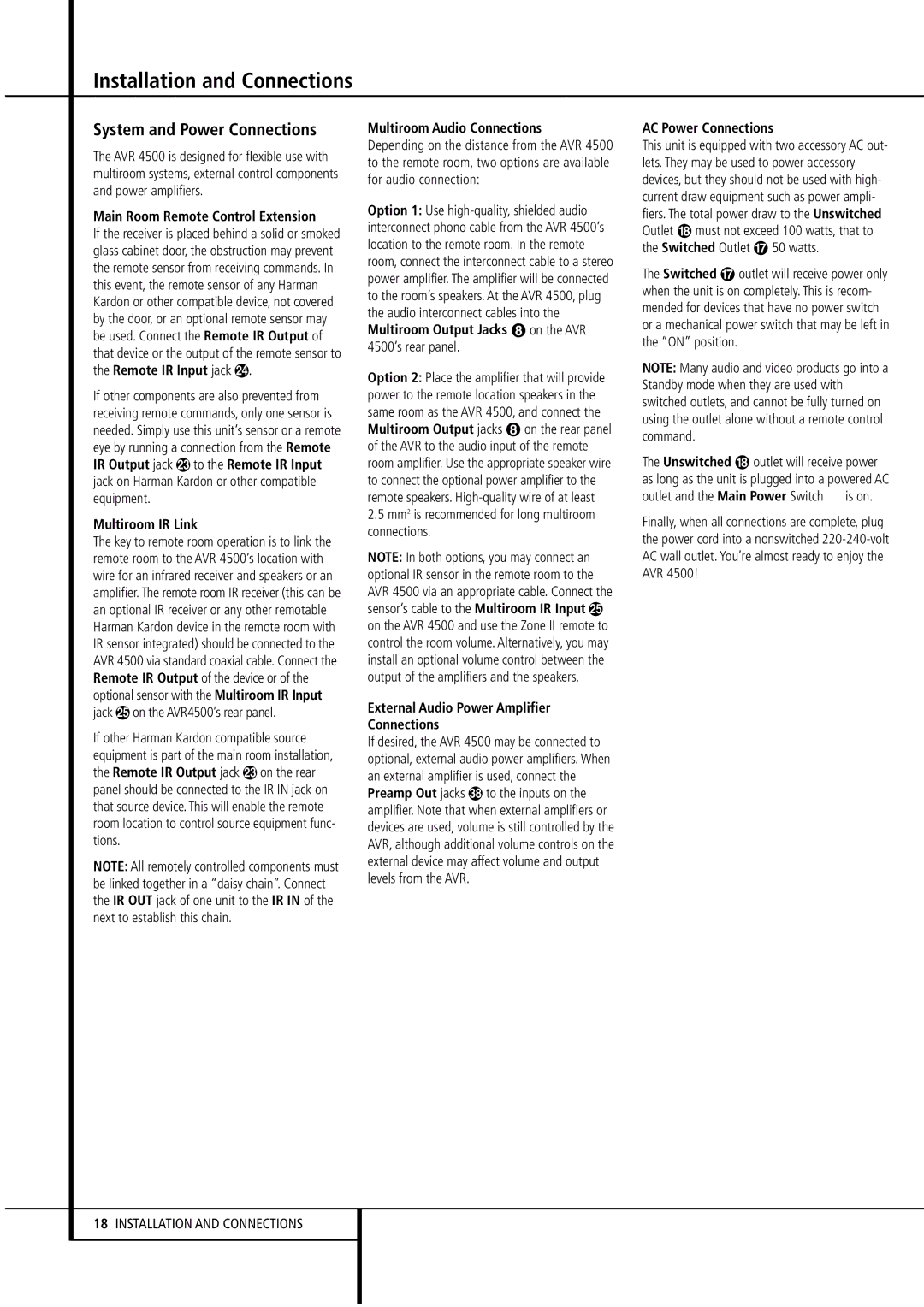
AVR4500 specifications
The Harman-Kardon AVR4500 is a high-performance AV receiver designed to deliver an immersive audio and visual experience for home theater enthusiasts. With its robust specifications and advanced technology, the AVR4500 stands out as a leading choice for those seeking exceptional sound quality and versatility.One of the key features of the AVR4500 is its support for multiple audio formats. It is compatible with Dolby Atmos, DTS:X, and other advanced audio technologies, allowing for three-dimensional soundscapes that enhance the cinematic experience. The receiver is equipped with a 9.2-channel configuration, providing ample power and flexibility to drive various speaker setups, including surround sound systems.
The AVR4500 uses Harman's proprietary MultEQ XT32 room calibration technology. This system intelligently analyzes the acoustics of the room and automatically adjusts the sound output to optimize listening conditions. This ensures that users hear their content as intended, regardless of the environment.
In terms of connectivity, the AVR4500 is equipped with a wide range of HDMI inputs and outputs, supporting 4K Ultra HD video and HDR formats such as Dolby Vision and HDR10. This ensures that users can experience the latest high-definition content with stunning clarity and detail. The receiver also features HDMI eARC support, allowing for high-quality audio return channels for compatible TVs.
The AVR4500 supports various streaming services, enabling users to access their favorite music and podcasts effortlessly. With built-in Wi-Fi and Bluetooth, users can stream audio directly from their smartphones or tablets. Additionally, integration with popular voice assistants makes controlling the receiver convenient and user-friendly.
Another notable characteristic of the AVR4500 is its robust power output. It is designed to deliver high-fidelity audio across all channels, ensuring that every sound is clear and richly detailed. With a stylish design featuring a premium finish, this receiver not only performs exceptionally but also adds an elegant touch to any entertainment setup.
Overall, the Harman-Kardon AVR4500 combines cutting-edge technology, outstanding audio performance, and versatile connectivity options, making it an excellent choice for anyone looking to enhance their home theater experience. Whether for movie nights, gaming sessions, or music playback, the AVR4500 offers the quality and performance that audiophiles demand.

