Figure 5.2 Connect Incoming Gas Line to Manual Shutoff Valve
•Accessibility to the shutoff valve is required after installation, or another accessible shutoff is required.
•The flex line and gas shutoff valve can be accessed after installation by removing four screws from the valve mounting bracket at the rear of the control box.
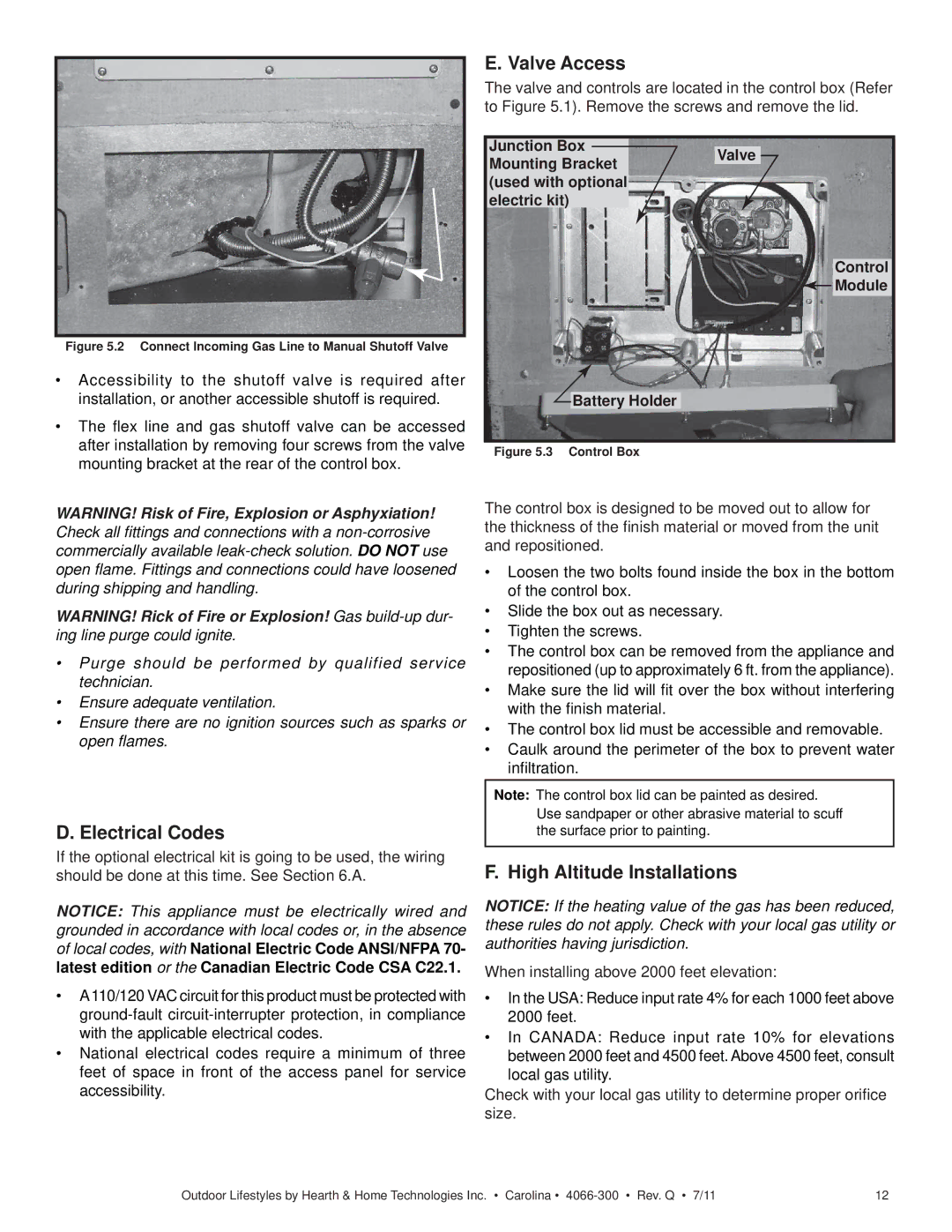
E. Valve Access
The valve and controls are located in the control box (Refer to Figure 5.1). Remove the screws and remove the lid.
Junction Box
Mounting BracketValve (used with optional
electric kit)
Control
![]() Module
Module
Battery Holder
Figure 5.3 Control Box
WARNING! Risk of Fire, Explosion or Asphyxiation! Check all fittings and connections with a
WARNING! Rick of Fire or Explosion! Gas
•Purge should be performed by qualified service technician.
•Ensure adequate ventilation.
•Ensure there are no ignition sources such as sparks or open flames.
D.Electrical Codes
If the optional electrical kit is going to be used, the wiring should be done at this time. See Section 6.A.
NOTICE: This appliance must be electrically wired and grounded in accordance with local codes or, in the absence of local codes, with National Electric Code ANSI/NFPA 70- latest edition or the Canadian Electric Code CSA C22.1.
•A110/120 VAC circuit for this product must be protected with
•National electrical codes require a minimum of three feet of space in front of the access panel for service accessibility.
The control box is designed to be moved out to allow for the thickness of the finish material or moved from the unit and repositioned.
•Loosen the two bolts found inside the box in the bottom of the control box.
•Slide the box out as necessary.
•Tighten the screws.
•The control box can be removed from the appliance and repositioned (up to approximately 6 ft. from the appliance).
•Make sure the lid will fit over the box without interfering with the finish material.
•The control box lid must be accessible and removable.
•Caulk around the perimeter of the box to prevent water infiltration.
Note: The control box lid can be painted as desired. Use sandpaper or other abrasive material to scuff the surface prior to painting.
F. High Altitude Installations
NOTICE: If the heating value of the gas has been reduced, these rules do not apply. Check with your local gas utility or authorities having jurisdiction.
When installing above 2000 feet elevation:
•In the USA: Reduce input rate 4% for each 1000 feet above 2000 feet.
•In CANADA: Reduce input rate 10% for elevations between 2000 feet and 4500 feet. Above 4500 feet, consult local gas utility.
Check with your local gas utility to determine proper orifice size.
Outdoor Lifestyles by Hearth & Home Technologies Inc. • Carolina • | 12 |