Direct Vent Gas Appliance
Installation and Operation
Models CD4236R CD4842R CD4236LR CD4842LR CD4236IR CD4842IR
What to do if you smell gas
Congratulations
Homeowner Reference Information
Table of Contents
Installer Guide
User Guide
Finishing
Appliance Setup
Troubleshooting
Reference Materials
Warranty Hearth & Home Technologies Limited Warranty
CONDITIONS, Exclusions & Limitation of Liability
Warranty
Listing and Code Approvals
Requirements for the Commonwealth of Massachusetts
Gas Fireplace Safety
Operating Instructions
Your Fireplace
Fan Kit optional
Fixed Glass Assembly
Remote Controls, Wall Controls and Wall Switches
Clear Space
For Your Safety Read Before Lighting
Lighting Instructions IPI
Lighting
Standing
Pilot
Frequently Asked Questions
After Fireplace is Lit
Remote Control
Maintenance and Service
Maintenance Tasks-Homeowner
Doors, Surrounds, Fronts
Maintenance Tasks-Qualified Service Technician
Getting Started
Typical Appliance System
Inspect Appliance and Components
Design and Installation Considerations
Tools and Supplies Needed
Any such action may cause a fire hazard
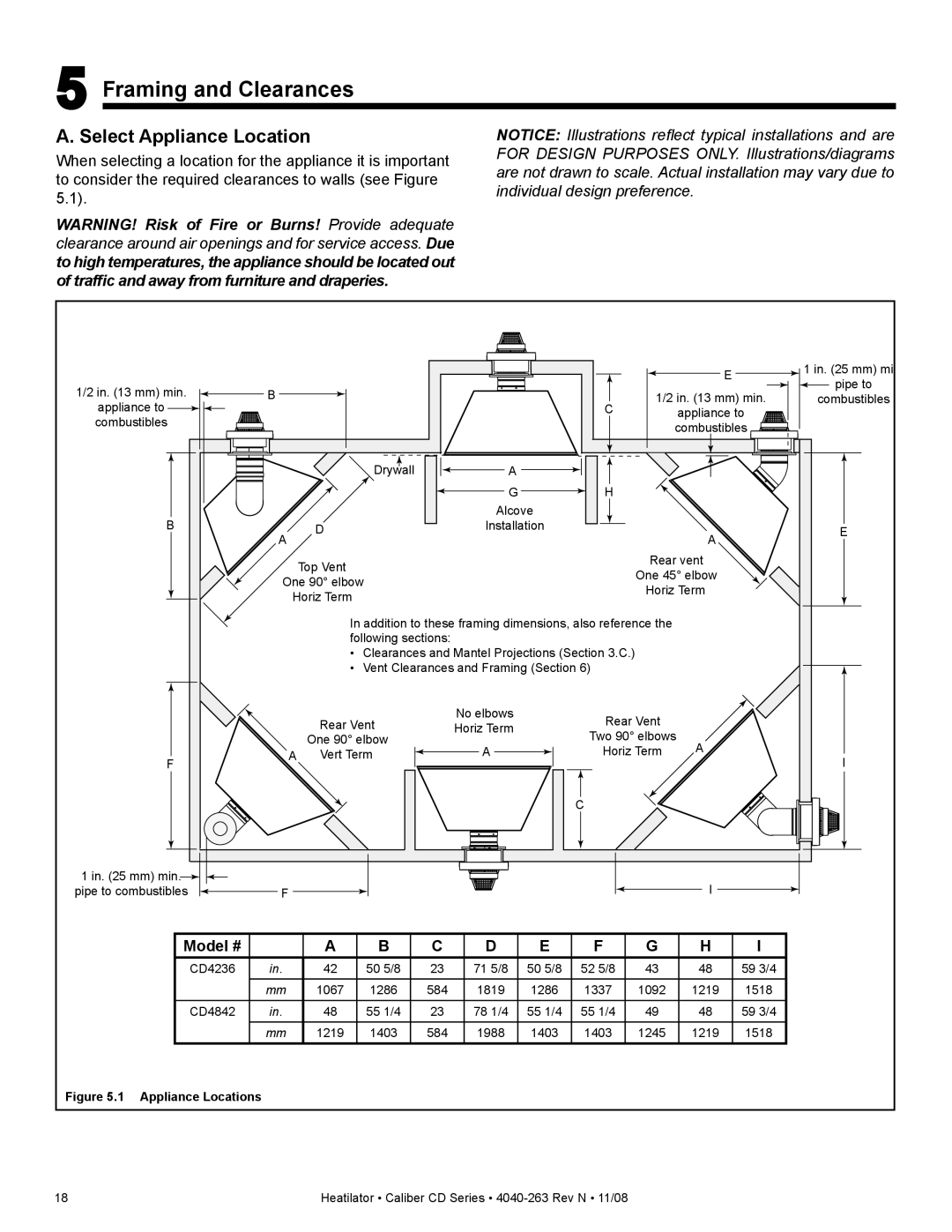
Framing and Clearances
Select Appliance Location
Model #
Construct the Appliance Chase
Clearances
Rough Opening Model Width Height Depth
Mantel and Wall Projections
Mantels
Mantel Legs or Wall Projections
Termination Locations
Vent Termination Minimum Clearances
Minimum Clearances for Termination
Vent Table Key
Vent Information and Diagrams
Approved Pipe
Use of Elbows
Vent Diagrams
Top Vent Horizontal Termination
One Elbow
Two 45 Elbows replacing One 90 Elbow
Two Elbows
Min Max +H 2 max +H 2+H 3 max
Installed Vertically
Three Elbows
Top Vent Vertical Termination
No Elbow
12 ft 3.66 m min 60 ft 18.29 m max
Rear Vent Horizontal Termination
One 45 Elbow
Two Elbows
Rear Vent Vertical Termination
Min Ft 1.83 m max 12 ft 3.66 m min 60 ft 18.29 m max
Install Vertical Termination Baffle
17 Flat Baffle
Wall Penetration Framing
Vent Clearances and Framing
Pipe Clearances to Combustibles
Combustible Wall Penetration
Install the Ceiling Firestop
Installing Ceiling Firestop
Install Attic Insulation Shield
Flat Ceiling Installation
Vaulted Ceiling Installation
Appliance Preparation
Convert from Top Vent to Rear Vent
Outer Collar, Remove Four Screws
11 Place Outer Collar on Rear of Appliance
16 Cover Plate-Replace
Secure and Level the Appliance
20 Proper Positioning, Leveling And Securing Of An
Assemble Pipe Sections DVP Only
Install Vent Pipe
Attach Pipe to the Firebox Assembly
Assemble Pipe Sections
Assemble Vent Sections SLP Only
Assemble Slip Sections
Secure the Vent Sections
Disassemble Vent Sections
Install Decorative Ceiling Components SLP only
Install Metal Roof Flashing
Assemble and Install Storm Collar
Caulk
Install RF4-8
SLP-FS
Install Vertical Termination Cap
Install Decorative Wall Components SLP only
Heat Shield Requirements for Horizontal Termination
Install Horizontal Termination Cap
Interior
Gas Pressure
Gas Information
Fuel Conversion
Gas Connection
Intellifire Ignition System Wiring
Wiring Requirements
Standing Pilot Ignition System Wiring
Optional Accessories Requirements
Electrical Service and Repair
WSK-MLT-HTL
Junction Box Installation
Wall Switch Installation for Fan Optional
Finishing
Facing Material
Combustible
Appliance Setup
Air Shutter Setting
Install Trim and/or Surround
Install Hood
Removing Fixed Glass Assembly
Troubleshooting
Symptom Possible Causes Corrective Action
Standing Pilot Ignition System
Symptom Possible Cause Corrective Action
Intellifire Ignition System
Will not ignite. If the pilot
Appliance Dimension Diagram
Reference Materials
Vent Components Diagrams
DVP Vent Components
BEK DVP-BEK2
DVP-TVHW
DVP-TRAP
Horizontal Termination Cap
DVP-HRC-SS
Effective
SL-2DVP
Adapter
Service Parts
CD4236IR, CD4236ILR
Service
CD4236R, CD4236LR
IPI Valve Assembly
CD4842IR, CD4842ILR
CD4842R, CD4842LR
IPI Valve Assembly
Optional Components
Model # Description
FFCM36BN
This page intentionally left blank
This page intentionally left blank
This page intentionally left blank
Contact Information