8 Vent Clearances and Framing
A. Pipe Clearances to Combustibles
WARNING! Risk of Fire! Maintain air space clearance to vent. DO NOT pack insulation or other combustibles:
•Between ceiling firestops
•Between wall shield firestops
•Around vent system
Failure to keep insulation or other material away from vent pipe may cause over heating and fire.
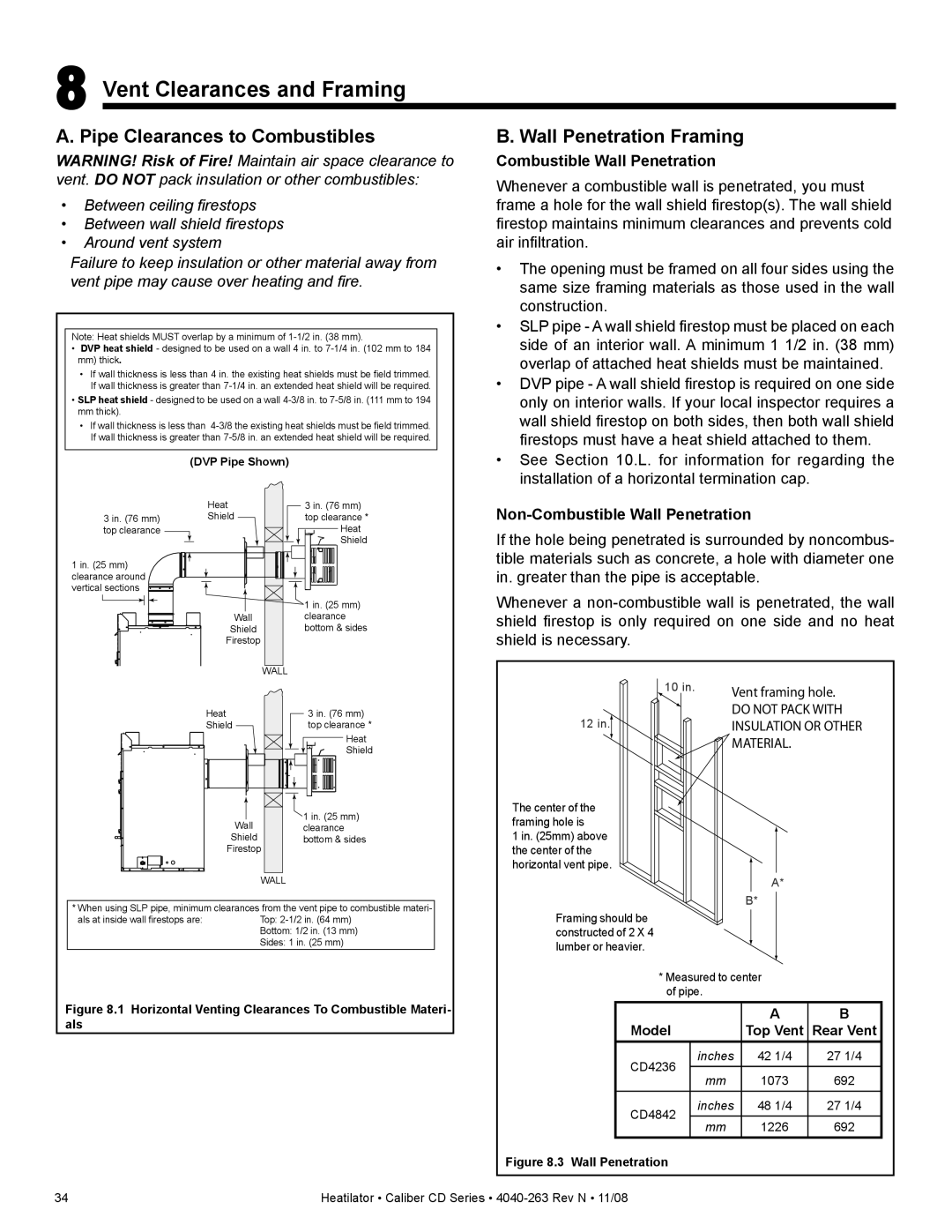
Note: Heat shields MUST overlap by a minimum of
•DVP heat shield - designed to be used on a wall 4 in. to
mm)thick.
•If wall thickness is less than 4 in. the existing heat shields must be field trimmed. If wall thickness is greater than
•SLP heat shield - designed to be used on a wall
•If wall thickness is less than
(DVP Pipe Shown)
B. Wall Penetration Framing
Combustible Wall Penetration
Whenever a combustible wall is penetrated, you must frame a hole for the wall shield firestop(s). The wall shield firestop maintains minimum clearances and prevents cold air infiltration.
•The opening must be framed on all four sides using the same size framing materials as those used in the wall construction.
•SLP pipe - A wall shield firestop must be placed on each side of an interior wall. A minimum 1 1/2 in. (38 mm) overlap of attached heat shields must be maintained.
•DVP pipe - A wall shield firestop is required on one side only on interior walls. If your local inspector requires a wall shield firestop on both sides, then both wall shield firestops must have a heat shield attached to them.
•See Section 10.L. for information for regarding the installation of a horizontal termination cap.
3 in. (76 mm) top clearance
1 in. (25 mm) clearance around vertical sections
Heat
Shield
Wall
Shield
Firestop
3 in. (76 mm) top clearance *
Heat
Shield
1 in. (25 mm) clearance bottom & sides
Non-Combustible Wall Penetration
If the hole being penetrated is surrounded by noncombus- tible materials such as concrete, a hole with diameter one in. greater than the pipe is acceptable.
Whenever a
WALL
Heat
Shield
Wall
Shield
Firestop
3 in. (76 mm) top clearance *
Heat
Shield
![]() 1 in. (25 mm) clearance bottom & sides
1 in. (25 mm) clearance bottom & sides
| 10 in. | Vent framing hole. |
|
| |
12 in. |
| DO NOT PACK WITH |
| INSULATION OR OTHER |
MATERIAL.
The center of the framing hole is
1 in. (25mm) above the center of the horizontal vent pipe.
WALL
* When using SLP pipe, minimum clearances from the vent pipe to combustible materi-
als at inside wall firestops are:Top:
Figure 8.1 Horizontal Venting Clearances To Combustible Materi- als
A*
B*
Framing should be constructed of 2 X 4 lumber or heavier.
*Measured to center of pipe.
|
| A | B | |
Model |
| Top Vent | Rear Vent | |
CD4236 | inches | 42 1/4 | 27 1/4 | |
|
|
| ||
mm | 1073 | 692 | ||
| ||||
|
|
|
| |
CD4842 | inches | 48 1/4 | 27 1/4 | |
mm | 1226 | 692 | ||
|
Figure 8.3 Wall Penetration
34 | Heatilator • Caliber CD Series • |