7 Electrical Information
A. Ignition System Wiring
•This fireplace is equipped with an electronic ignition system which operates on a 6 volt system.
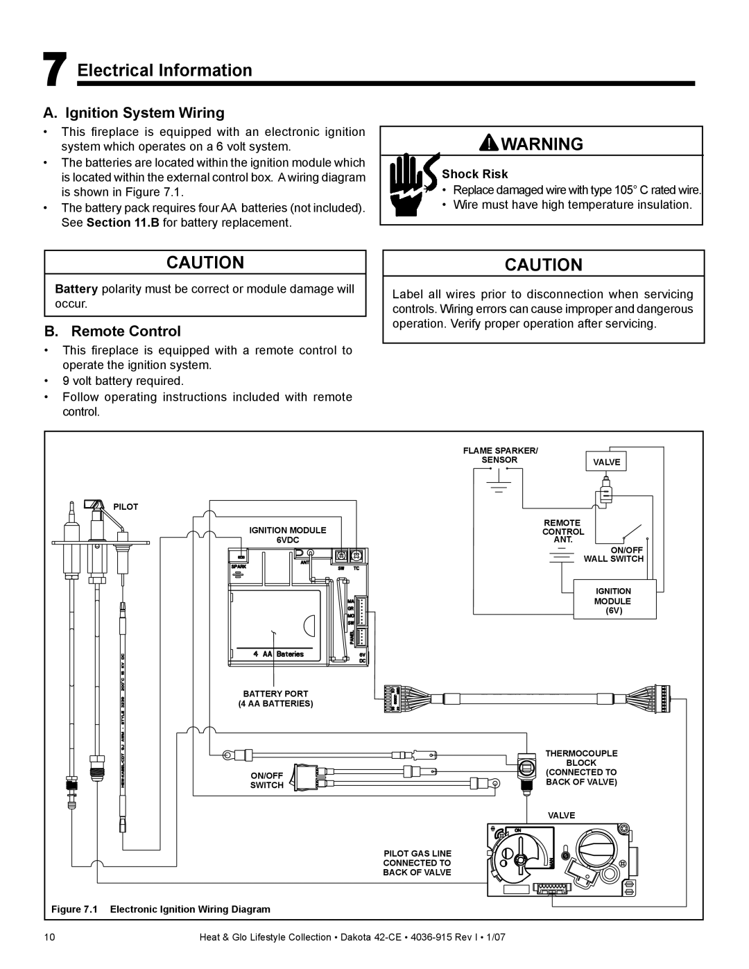
•The batteries are located within the ignition module which is located within the external control box. A wiring diagram is shown in Figure 7.1.
•The battery pack requires four AA batteries (not included). See Section 11.B for battery replacement.
![]() WARNING
WARNING
Shock Risk
•Replace damaged wire with type 105° C rated wire.
•Wire must have high temperature insulation.
CAUTION
Battery polarity must be correct or module damage will occur.
B. Remote Control
•This fireplace is equipped with a remote control to operate the ignition system.
•9 volt battery required.
•Follow operating instructions included with remote control.
CAUTION
Label all wires prior to disconnection when servicing controls. Wiring errors can cause improper and dangerous operation. Verify proper operation after servicing.
| FLAME SPARKER/ |
|
| SENSOR | VALVE |
| PILOT |
|
| IGNITION MODULE | REMOTE |
| CONTROL | |
| 6VDC | ANT. |
|
| ON/OFF |
|
| WALL SWITCH |
|
| IGNITION |
|
| MODULE |
|
| (6V) |
| BATTERY PORT |
|
| (4 AA BATTERIES) |
|
|
| THERMOCOUPLE |
|
| BLOCK |
| ON/OFF | (CONNECTED TO |
| BACK OF VALVE) | |
| SWITCH | |
|
| |
|
| VALVE |
| PILOT GAS LINE |
|
| CONNECTED TO |
|
| BACK OF VALVE |
|
Figure 7.1 Electronic Ignition Wiring Diagram |
| |
10 | Heat & Glo Lifestyle Collection • Dakota |
|