Remote Control Wiring Diagrams
|
|
| IGNITION MODULE 3 VAC |
|
|
|
| ||
110V |
|
|
|
| I |
|
|
| INTERMITTENT |
|
|
|
|
|
|
|
| ||
|
|
|
|
|
|
|
|
| PILOT IGNITOR |
REMOTE RECEIVER |
|
|
|
| S |
|
|
|
|
|
|
|
|
|
|
|
|
| |
TRANSFORMER |
|
|
|
|
|
| WHITE |
|
|
3 VAC |
|
|
|
|
|
|
|
|
|
|
|
|
|
|
|
| ORANGE |
|
|
|
|
|
|
| K | GROUND TO |
|
| |
|
|
|
| C |
|
|
|
| |
|
|
| A |
| FIREPLACE |
|
| ||
|
| L |
|
|
|
| |||
PLUG IN |
| B |
|
|
|
|
| ||
|
|
|
|
| CHASSIS |
|
| ||
|
| D |
|
|
|
|
|
|
|
| E |
|
|
|
|
|
|
| |
| R |
|
|
|
|
|
|
|
|
|
|
|
|
| JUMPER WIRE |
|
|
| |
|
|
|
|
| (TO BROWN) | ORANGE |
| GREEN | |
|
|
|
|
|
|
| VALVE | ||
BATTERY PACK |
|
|
|
|
|
|
|
|
|
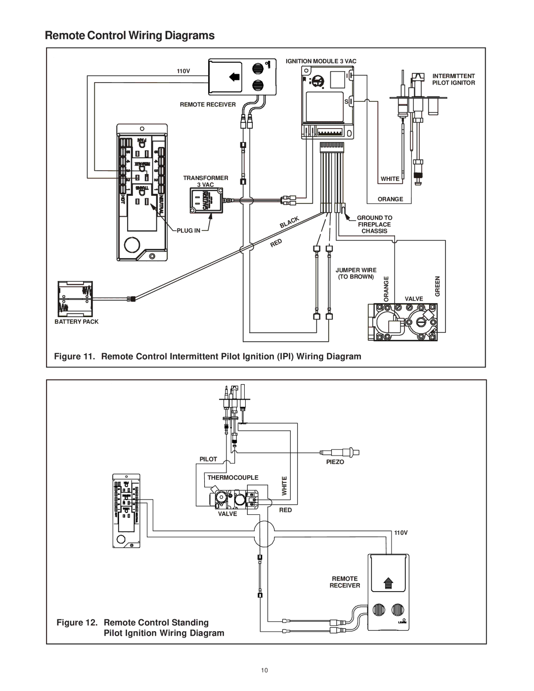
Figure 11. Remote Control Intermittent Pilot Ignition (IPI) Wiring Diagram |
|
|
| ||||||
PILOT |
|
|
|
| PIEZO |
|
|
|
|
|
|
|
|
|
|
|
|
| |
THERMOCOUPLE |
| WHITE |
|
|
|
|
|
| |
|
|
|
|
|
|
|
| ||
VALVE |
| RED |
|
|
|
|
| ||
|
|
|
|
|
|
|
|
| |
|
|
|
|
|
|
| 110V |
| |
|
|
|
|
| REMOTE |
|
|
| |
|
|
|
|
| RECEIVER |
|
|
| |
Figure 12. Remote Control Standing
Pilot Ignition Wiring Diagram
10