Wiring Electronic Spark Ignitions
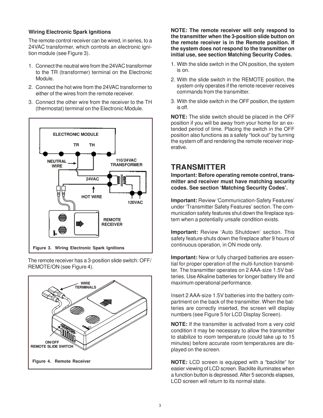
The remote control receiver can be wired, in series, to a 24VAC transformer, which controls an electronic igni- tion module (see Figure 3).
1.Connect the neutral wire from the 24VAC transformer to the TR (transformer) terminal on the Electronic Module.
2.Connect the hot wire from the 24VAC transformer to either of the wires from the remote receiver.
3.Connect the other wire from the receiver to the TH (thermostat) terminal on the Electronic Module.
ELECTRONIC MODULE
TR | TH |
NEUTRAL | 110/24VAC |
WIRE | TRANSFORMER |
| 24VAC |
| HOT WIRE |
| 120VAC |
| REMOTE |
| RECEIVER |
Figure 3. Wiring Electronic Spark Ignitions
The remote receiver has a
WIRE |
TERMINALS |
ON/OFF |
REMOTE SLIDE SWITCH |
Figure 4. Remote Receiver |
NOTE: The remote receiver will only respond to the transmitter when the
1.With the slide switch in the ON position, the system is on.
2.With the slide switch in the REMOTE position, the system only operates if the remote receiver receives commands from the transmitter.
3.With the slide switch in the OFF position, the system is off.
NOTE: The slide switch should be placed in the OFF position if you will be away from your home for an ex- tended period of time. Placing the switch in the OFF position also functions as a safety “lock out” by turning the system off and rendering the remote receiver inop- erative.
TRANSMITTER
Important: Before operating remote control, trans- mitter and receiver must have matching security codes. See section ‘Matching Security Codes’.
Important: Review
Important: Review ‘Auto Shutdown’ section. This safety feature shuts down the fireplace after 9 hours of continuous operation, in ON mode only.
Important: New or fully charged batteries are essen- tial for proper operation of the
Insert 2
NOTE: If the transmitter is activated from a very cold condition it may be necessary to allow the transmitter to stabilize to room temperature (could take up to 15 minutes) before accurate room temperatures are dis- played on the screen.
NOTE: LCD screen is equipped with a “backlite” for easier viewing of LCD screen. Backlite illuminates when a function button is depressed. After 5 seconds elapses, LCD screen will return to its normal state.
3