HRV200PLUS Control Wiring
The 6100PLUS is designed to operate as a system with the HRV200PLUS. Six
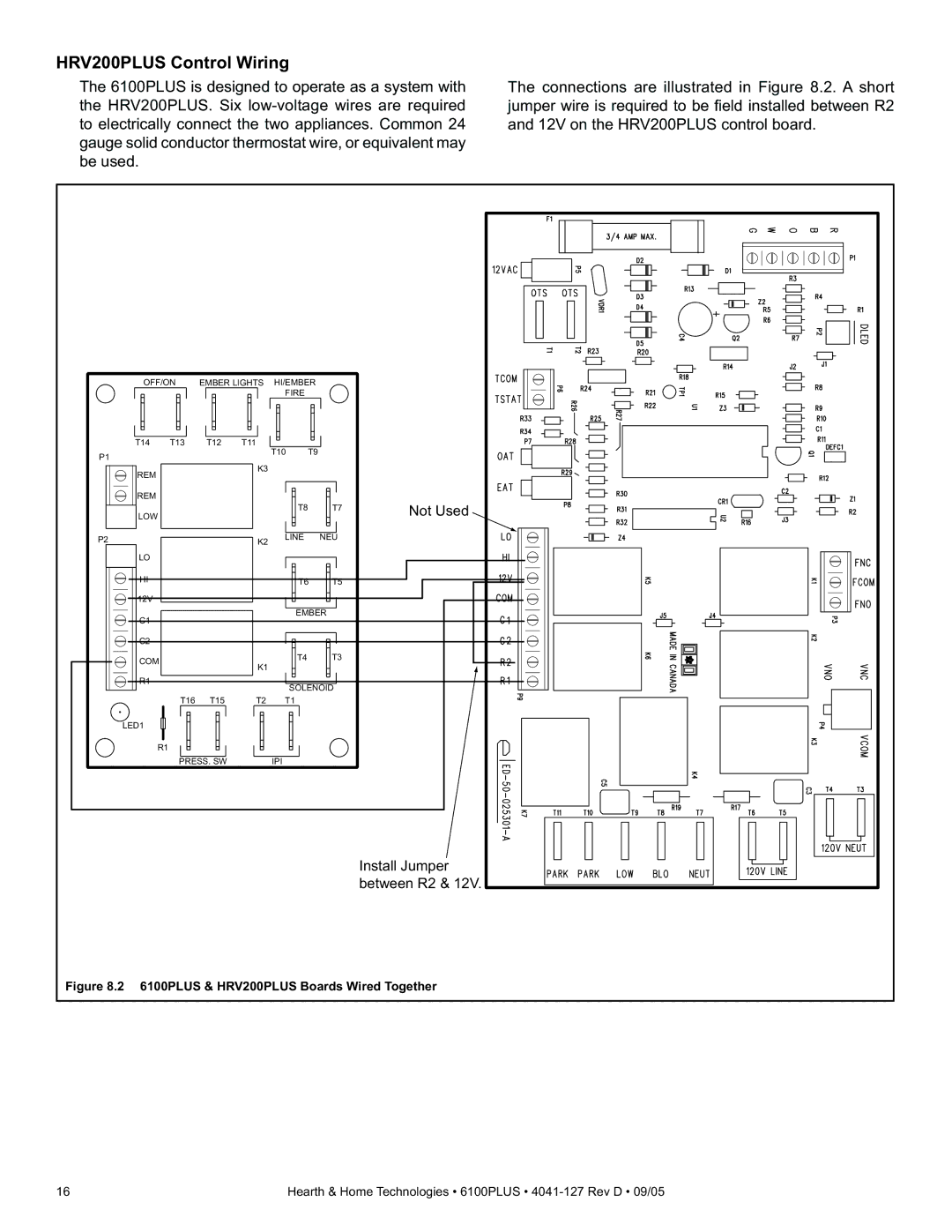
The connections are illustrated in Figure 8.2. A short jumper wire is required to be fi eld installed between R2 and 12V on the HRV200PLUS control board.
OFF/ON | EMBER LIGHTS | HI/EMBER |
|
| |||
|
|
|
| FIRE |
|
| |
T14 | T13 | T12 | T11 | T10 | T9 |
|
|
P1 |
|
|
|
|
| ||
|
| K3 |
|
|
|
| |
REM |
|
|
|
|
|
| |
|
|
|
|
|
|
| |
REM |
|
|
|
|
|
| Not Used |
LOW |
|
|
|
| T8 | T7 | |
|
|
|
|
|
| ||
P2 |
|
| K2 | LINE | NEU |
| |
LO |
|
|
|
|
|
|
|
HI |
|
|
|
| T6 | T5 |
|
12V |
|
|
|
|
|
|
|
C1 |
|
|
|
| EMBER |
| |
|
|
|
|
|
|
| |
C2 |
|
|
|
|
|
|
|
COM |
|
| K1 |
| T4 | T3 |
|
|
|
|
|
|
| ||
|
|
|
|
|
|
| |
R1 |
|
|
|
| SOLENOID |
| |
|
|
|
|
|
| ||
| T16 | T15 | T2 | T1 |
|
| |
LED1 |
|
|
|
|
|
|
|
R1 |
|
|
|
|
|
|
|
| PRESS. SW |
| IPI |
|
|
| |
|
|
|
|
|
|
| Install Jumper |
|
|
|
|
|
|
| between R2 & 12V. |
Figure 8.2 6100PLUS & HRV200PLUS Boards Wired Together
16 | Hearth & Home Technologies • 6100PLUS • |