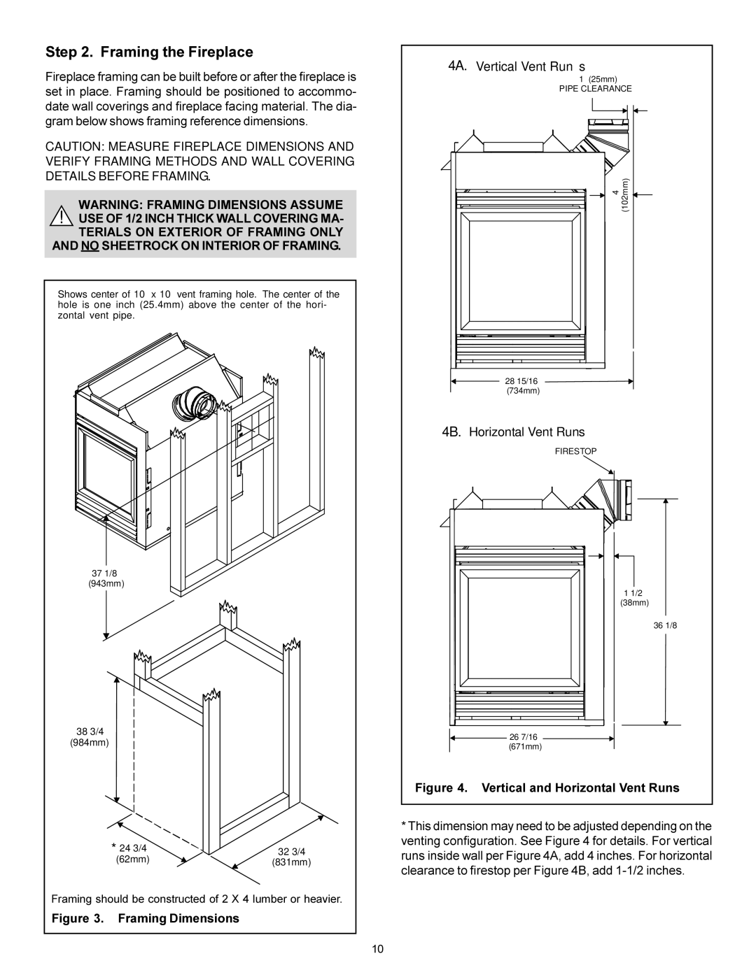
BAY-38HV specifications
The Heat & Glo LifeStyle BAY-38HV is a cutting-edge gas fireplace designed to enhance the ambience of any home while providing efficiency and convenience. This innovative unit combines modern aesthetics with advanced technology, making it a popular choice among homeowners seeking both form and function in their heating solutions.One of the standout features of the BAY-38HV is its sleek, contemporary design, which allows it to seamlessly integrate into various interior styles. With its clean lines and expansive viewing area, the fireplace creates a focal point in any room, offering a warm and inviting atmosphere. The heat-resistant glass front provides a clear view of the flames, ensuring that the beauty of the fire can be enjoyed from multiple angles.
In terms of technology, the BAY-38HV is equipped with the latest in gas fireplace innovations. It incorporates an advanced IntelliFire ignition system, allowing for easy operation with the simple push of a button. Users can control the flame height and heat output directly from a remote, providing complete convenience and customizability. This makes it an excellent option for those who want to adjust the ambiance of their space effortlessly.
Efficiency is another key characteristic of the BAY-38HV. The fireplace boasts a high efficiency rating, ensuring that the warmth generated is maximized while minimizing energy consumption. This efficient performance not only contributes to a more comfortable home but also helps in reducing heating costs, making it an environmentally friendly choice.
The BAY-38HV also features an array of customizable options, including various log styles and ember bed choices. This allows homeowners to tailor the appearance of their fireplace to suit their individual preferences. Additionally, its compatibility with zone heating systems offers an effective solution for those looking to heat specific areas of their home without relying on central heating.
Safety is paramount with the Heat & Glo LifeStyle BAY-38HV. It includes protective features such as a safety screen and automatic shut-off mechanisms, providing peace of mind for families and individuals.
In summary, the Heat & Glo LifeStyle BAY-38HV gas fireplace is an exemplary model that combines stylish design with advanced technology. Its ease of use, efficiency, customization options, and safety features make it an ideal choice for anyone looking to enhance their living space with the charm and comfort of a gas fireplace.

