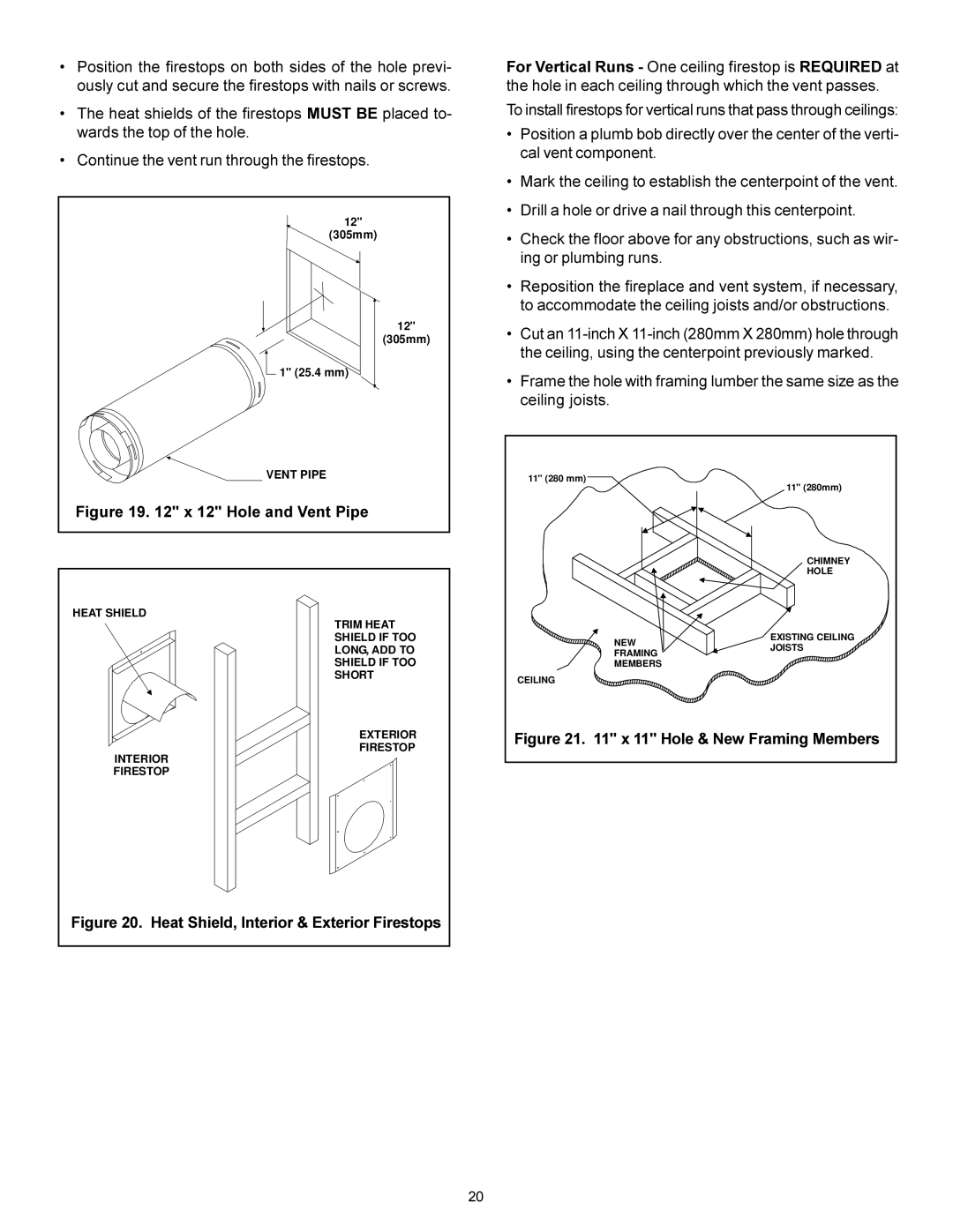
•Position the firestops on both sides of the hole previ- ously cut and secure the firestops with nails or screws.
•The heat shields of the firestops MUST BE placed to- wards the top of the hole.
•Continue the vent run through the firestops.
12" |
(305mm) |
12" |
(305mm) |
1" (25.4 mm) |
VENT PIPE |
Figure 19. 12" x 12" Hole and Vent Pipe |
HEAT SHIELD
TRIM HEAT SHIELD IF TOO LONG, ADD TO SHIELD IF TOO SHORT
EXTERIOR
FIRESTOP
INTERIOR
FIRESTOP
Figure 20. Heat Shield, Interior & Exterior Firestops
For Vertical Runs - One ceiling firestop is REQUIRED at the hole in each ceiling through which the vent passes.
To install firestops for vertical runs that pass through ceilings:
•Position a plumb bob directly over the center of the verti- cal vent component.
•Mark the ceiling to establish the centerpoint of the vent.
•Drill a hole or drive a nail through this centerpoint.
•Check the floor above for any obstructions, such as wir- ing or plumbing runs.
•Reposition the fireplace and vent system, if necessary, to accommodate the ceiling joists and/or obstructions.
•Cut an
•Frame the hole with framing lumber the same size as the ceiling joists.
11" (280 mm) | 11" (280mm) | |
| ||
| CHIMNEY | |
| HOLE | |
NEW | EXISTING CEILING | |
JOISTS | ||
FRAMING | ||
| ||
MEMBERS |
| |
CEILING |
| |
Figure 21. 11" x 11" Hole & New Framing Members | ||
20