B. Installing Vent Components
After determining which set of starting collars will be used (top or rear), follow venting instructions accordingly.
Venting Out the Rear Vent
Remove the installed rear seal cap from the rear starting collars by cutting the strap at each end. (see Figure 15). Follow the vent configuration tables accordingly.
Remove the insulation from the REAR five inch flue, pull the heat shield out from outside of the firebox.
!WARNING: THE TOP HEAT SHIELD (INSIDE THE FIREBOX) MUST REMAIN ATTACHED IF THE VENT SYSTEM IS ATTACHED TO THE REAR STARTING COLLARS. SEE FIGURE 15.
Venting Out the Top Vent
Remove the two screws in the top vent collar seal cap and remove the top vent collar seal cap and two pieces of in- sulation inside the top two starting collars (See Figure 15).
Remove the heat shield from inside the TOP five inch flue from outside of the firebox.
The glass must be taken off again for positioning the logs when the unit is finally installed in place and finished around it.
!WARNING: THE REAR VENT COLLAR SEAL CAP MUST REMAIN ATTACHED TO THE REAR VENT COLLARS IF THE VENT SYSTEM IS AT- TACHED TO THE TOP STARTING COLLARS.
!WARNING: FAILURE TO REMOVE INSULATION IN THE SET OF COLLARS YOU ARE USING COULD CAUSE A FIRE.
!WARNING: YOU MUST LEAVE THE INSULATION IN PLACE IN THE SET OF COLLARS YOU ARE NOT USING.
If your vertical vent component is over 10 feet, you may want to install the vertical baffle (located in the bag containing the install manual) to improve flame appearance. Center the vertical baffle on the 5” flue being used, and with self tapping screws secure the baffle to the inside of the firebox.
Venting Out Rear | Venting Out Top | |
SEAL | SEAL |
|
CAP | CAP |
|
HEAT | INSULATION |
|
SHIELD |
| |
| DISCARD BOTH |
|
| PIECES and |
|
| HEAT SHIELD | HEAT |
DISCARD |
| SHIELD |
INSULATION |
|
|
and |
|
|
HEAT SHIELD |
|
|
Insert screwdriver |
|
|
or similar object |
|
|
here to remove cap. | CUT |
|
|
| |
| HERE | |
Figure 15 |
|
|
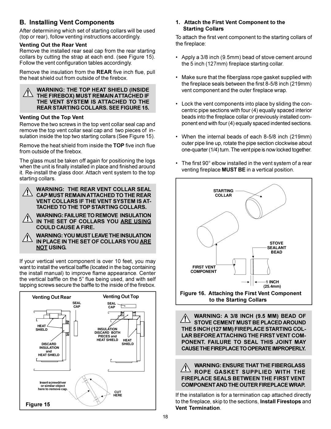
1.Attach the First Vent Component to the Starting Collars
To attach the first vent component to the starting collars of the fireplace:
•Apply a 3/8 inch (9.5mm) bead of stove cement around the 5 inch (127mm) fireplace starting collar.
•Make sure that the fiberglass rope gasket supplied with the fireplace seals between the first
•Lock the vent components into place by sliding the con- centric pipe sections with four (4) equally spaced interior beads into the fireplace collar or previously installed com- ponent end with four (4) equally spaced indented sections.
•When the internal beads of each
•The first 90° elbow installed in the vent system of a rear venting fireplace MUST BE in a vertical position.
STARTING
COLLAR
STOVE
SEALANT
BEAD
FIRST VENT
COMPONENT
![]() 1 INCH (25.4mm)
1 INCH (25.4mm)
Figure 16. Attaching the First Vent Component to the Starting Collars
!WARNING: A 3/8 INCH (9.5 MM) BEAD OF STOVE CEMENT MUST BE PLACED AROUND
THE 5 INCH (127 MM) FIREPLACE STARTING COL-
LAR BEFORE ATTACHING THE FIRST VENT COM- PONENT. FAILURE TO SEAL THIS JOINT MAY CAUSE THE FIREPLACE TO OPERATE IMPROPERLY.
!WARNING: ENSURE THAT THE FIBERGLASS ROPE GASKET SUPPLIED WITH THE
FIREPLACE SEALS BETWEEN THE FIRST VENT COMPONENT AND THE OUTER FIREPLACE WRAP.
If the installation is for a termination cap attached directly to the fireplace, skip to the sections, Install Firestops and Vent Termination.
18