Heat Controller, Inc. | HBH/V SERIES | Engineering Design Guide |
|
|
|
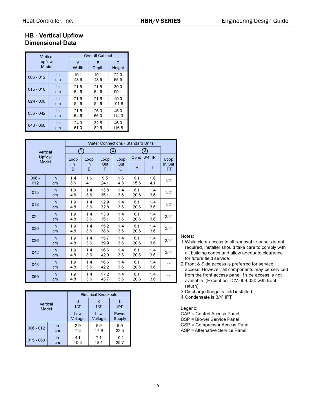
HB - Vertical Upflow
Dimensional Data
Vertical |
|
| Overall Cabinet |
|
|
|
|
| |||||||||||
upflow | A |
|
| B |
|
|
| C |
|
|
|
|
| ||||||
Model |
|
| Width |
|
| Depth |
|
| Height |
|
|
|
|
| |||||
|
|
|
|
|
|
|
|
|
|
|
|
|
|
|
|
|
|
|
|
006 - 012 |
| in | 19.1 |
|
| 19.1 |
|
| 22.0 |
|
|
|
|
| |||||
| cm | 48.5 |
|
| 48.5 |
|
| 55.9 |
|
|
|
|
| ||||||
|
|
|
|
|
|
|
|
|
|
|
| ||||||||
015 - 018 |
| in | 21.5 |
|
| 21.5 |
|
| 39.0 |
|
|
|
|
| |||||
| cm | 54.6 |
|
| 54.6 |
|
| 99.1 |
|
|
|
|
| ||||||
|
|
|
|
|
|
|
|
|
|
|
| ||||||||
024 - 030 |
| in | 21.5 |
|
| 21.5 |
|
| 40.0 |
|
|
|
|
| |||||
| cm | 54.6 |
|
| 54.6 |
|
| 101.6 |
|
|
|
|
| ||||||
|
|
|
|
|
|
|
|
|
|
|
| ||||||||
036 - 042 |
| in | 21.5 |
|
| 26.0 |
|
| 45.0 |
|
|
|
|
| |||||
| cm | 54.6 |
|
| 66.0 |
|
| 114.3 |
|
|
|
|
| ||||||
|
|
|
|
|
|
|
|
|
|
|
| ||||||||
048 - 060 |
| in | 24.0 |
|
| 32.5 |
|
| 46.0 |
|
|
|
|
| |||||
| cm | 61.0 |
|
| 82.6 |
|
| 116.8 |
|
|
|
|
| ||||||
|
|
|
|
|
|
|
|
|
|
|
| ||||||||
|
|
|
|
|
|
|
|
|
|
|
|
|
|
|
| ||||
|
|
|
|
|
|
|
| Water Connections - Standard Units |
| ||||||||||
Vertical |
|
| 1 |
|
|
|
|
|
| 2 |
|
| 3 |
| |||||
|
|
|
|
|
|
|
|
|
|
|
|
|
|
|
|
| |||
Upflow |
|
| Loop |
| Loop | Loop |
| Loop |
| Cond. 3/4” IPT | Loop | ||||||||
Model |
|
|
|
|
|
|
|
| |||||||||||
|
| In |
| In |
| Out |
| Out |
| H |
| I | In/Out | ||||||
|
|
|
|
|
|
|
|
|
| ||||||||||
|
|
|
|
| D |
| E |
| F |
| G |
|
| IPT | |||||
|
|
|
|
|
|
|
|
|
|
|
|
|
|
|
|
|
|
|
|
006 - |
|
| in |
| 1.4 |
| 1.6 |
| 9.5 |
|
|
| 1.6 | 6.1 |
| 1.6 | 1/2” | ||
012 |
|
| cm |
| 3.6 |
| 4.1 |
| 24.1 |
|
| 4.3 | 15.6 |
| 4.1 | ||||
|
|
|
|
|
|
|
|
| |||||||||||
015 |
|
| in |
| 1.9 |
| 1.4 |
| 13.8 |
|
| 1.4 | 8.1 |
| 1.4 | 1/2” | |||
|
| cm |
| 4.8 |
| 3.6 |
| 35.1 |
|
| 3.6 | 20.6 |
| 3.6 | |||||
|
|
|
|
|
|
|
|
|
| ||||||||||
018 |
|
| in |
| 1.9 |
| 1.4 |
| 12.9 |
|
| 1.4 | 8.1 |
| 1.4 | 1/2” | |||
|
| cm |
| 4.8 |
| 3.6 |
| 32.8 |
|
| 3.6 | 20.6 |
| 3.6 | |||||
|
|
|
|
|
|
|
|
|
| ||||||||||
024 |
|
| in |
| 1.9 |
| 1.4 |
| 13.8 |
|
| 1.4 | 8.1 |
| 1.4 | 3/4” | |||
|
| cm |
| 4.8 |
| 3.6 |
| 35.1 |
|
| 3.6 | 20.6 |
| 3.6 | |||||
|
|
|
|
|
|
|
|
|
| ||||||||||
030 |
|
| in |
| 1.9 |
| 1.4 |
| 15.2 |
|
| 1.4 | 8.1 |
| 1.4 | 3/4” | |||
|
| cm |
| 4.8 |
| 3.6 |
| 38.6 |
|
| 3.6 | 20.6 |
| 3.6 | |||||
|
|
|
|
|
|
|
|
|
| ||||||||||
036 |
|
| in |
| 1.9 |
| 1.4 |
| 15.7 |
|
| 1.4 | 8.1 |
| 1.4 | 3/4” | |||
|
| cm |
| 4.8 |
| 3.6 |
| 39.9 |
|
| 3.6 | 20.6 |
| 3.6 | |||||
|
|
|
|
|
|
|
|
|
| ||||||||||
042 |
|
| in |
| 1.9 |
| 1.4 |
| 16.6 |
|
| 1.4 | 8.1 |
| 1.4 | 3/4” | |||
|
| cm |
| 4.8 |
| 3.6 |
| 42.0 |
|
| 3.6 | 20.6 |
| 3.6 | |||||
|
|
|
|
|
|
|
|
|
| ||||||||||
048 |
|
| in |
| 1.9 |
| 1.4 |
| 16.6 |
|
| 1.4 | 8.1 |
| 1.4 | 1” | |||
|
| cm |
| 4.8 |
| 3.6 |
| 42.2 |
|
| 3.6 | 20.6 |
| 3.6 | |||||
|
|
|
|
|
|
|
|
|
| ||||||||||
060 |
|
| in |
| 1.9 |
| 1.4 |
| 17.2 |
|
| 1.4 | 8.1 |
| 1.4 | 1” | |||
|
| cm |
| 4.8 |
| 3.6 |
| 43.7 |
|
| 3.6 | 20.6 |
| 3.6 | |||||
|
|
|
|
|
|
|
|
|
| ||||||||||
|
|
|
|
|
|
|
|
|
|
|
|
| |||||||
|
|
|
|
| Electrical Knockouts |
|
|
|
|
| |||||||||
|
|
|
|
|
|
|
|
|
|
|
|
|
|
|
|
|
| ||
Vertical | J |
|
|
| K |
|
| L |
|
|
|
|
| ||||||
1/2” |
|
| 1/2” |
|
| 3/4” |
|
|
|
|
| ||||||||
Model |
|
|
|
|
|
|
|
|
|
|
| ||||||||
|
| Low |
|
| Low |
|
| Power |
|
|
|
|
| ||||||
|
|
|
|
|
|
|
|
|
|
|
|
|
| ||||||
|
|
|
|
| Voltage |
| Voltage |
|
| Supply |
|
|
|
|
| ||||
006 - 012 |
|
| in | 2.9 |
|
|
| 5.9 |
|
| 8.9 |
|
|
|
|
| |||
|
| cm | 7.3 |
|
|
| 14.9 |
|
| 22.5 |
|
|
|
|
| ||||
|
|
|
|
|
|
|
|
|
|
|
|
| |||||||
015 - 060 |
|
| in | 4.1 |
|
|
| 7.1 |
|
| 10.1 |
|
|
|
|
| |||
|
| cm | 10.5 |
|
| 18.1 |
|
| 25.7 |
|
|
|
|
| |||||
|
|
|
|
|
|
|
|
|
|
|
| ||||||||
Notes:
1.While clear access to all removable panels is not required, installer should take care to comply with all building codes and allow adequate clearance for future field service.
2.Front & Side access is preferred for service access. However, all components may be serviced from the front access panel if side access is not available. (Except on TCV
3.Discharge flange is field installed.
4.Condensate is 3/4” IPT.
Legend:
CAP = Control Access Panel
BSP = Blower Service Panel
CSP = Compressor Access Panel
ASP = Alternative Service Panel
26