Engineering Design Guide | HBH/V SERIES | Heat Controller, Inc. |
HBH & HBV COMPACT Horizontal & Vertical HFC-410a Units
Entering Water Temperature Range: 20 - 120°F
Horizontal Water Source Heat Pump |
|
| Vertical Water Source Heat Pump | |||||||||
Sizes |
|
|
|
|
|
|
| Sizes |
|
| ||
|
|
|
|
|
|
|
|
| 006 |
|
|
|
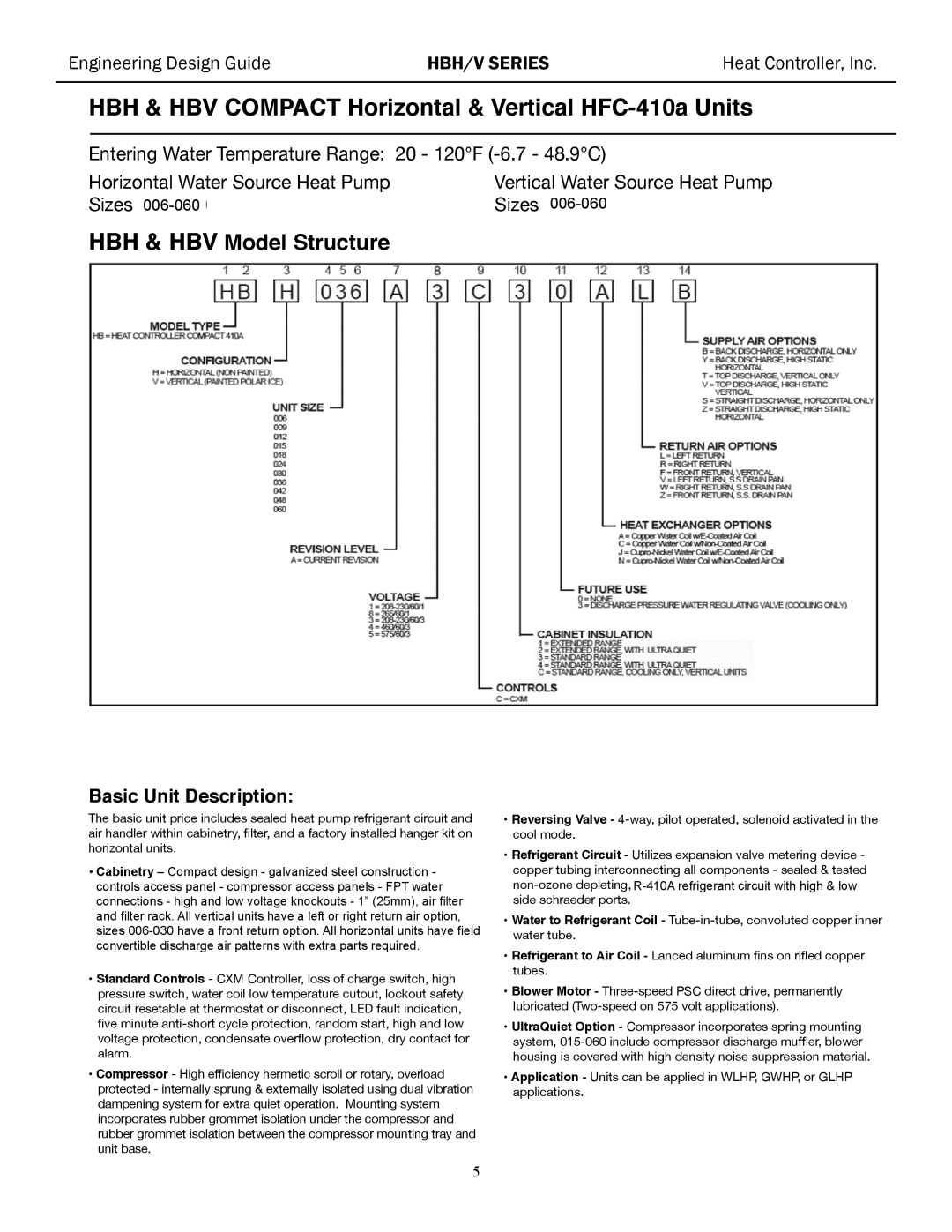
HBH & HBV Model Structure |
|
|
|
|
|
|
| |||||
1 | 2 | 3 | 4 | 5 | 6 | 7 | 9 | 10 | 11 | 12 | 13 | 14 |
H B H 0 3 6 A 3 C 3 0 A L B
MODEL TYPE
HB = HEAT CONTROLLER COMPACT 410A
CONFIGURATION
H = HORIZONTAL (NON PAINTED) }
V = VERTICAL (PAINTED POLAR ICE)
UNIT SIZE
015 - 1,8
018 - 1,8
024 - 1,3,4,8
030 - 1,3,4,8 Voltage Code
036 - 1,3,4,8
042 - 1,3,4,5
048 - 1,3,4,5
060 - 1,3,4,5
SUPPLY AIR OPTIONS
B = BACK DISCHARGE, HORIZONTAL ONLY Y = BACK DISCHARGE, HIGH STATIC
HORIZONTAL 018 - 060
T = TOP DISCHARGE, VERTICAL ONLY V = TOP DISCHARGE, HIGH STATIC
VERTICAL 018 - 060
S = STRAIGHT DISCHARGE, HORIZONTAL ONLY Z = STRAIGHT DISCHARGE, HIGH STATIC
HORIZONTAL 018 - 060
RETURN AIR OPTIONS
L = LEFT RETURN
R = RIGHT RETURN
F = FRONT RETURN, VERTICAL
V = LEFT RETURN, S.S DRAIN PAN W = RIGHT RETURN, S.S DRAIN PAN
Z = FRONT RETURN, S.S. DRAIN PAN
REVISION LEVEL
A = CURRENT REVISION FOR SIZES 006 - 060
VOLTAGE
1 =
8 = 265/60/1
3 =
4 = 460/60/3
5 = 575/60/3
Basic Unit Description:
HEAT EXCHANGER OPTIONS
A = Copper Water Coil
C = Copper Water Coil
J =
N =
FUTURE USE
0 = NONE
3 = DISCHARGE PRESSURE WATER REGULATING VALVE (COOLING ONLY) NOTAVAILABLE ON UNIT SIZES 006, 009 AND 012
CABINET INSULATION
3 = STANDARD RANGE
4 = STANDARD RANGE, WITH ULTRA QUIET
C = STANDARD RANGE, COOLING ONLY, VERTICAL UNITS
CONTROLS
C = CXM
The basic unit price includes sealed heat pump refrigerant circuit and air handler within cabinetry, lter, and a factory installed hanger kit on horizontal units.
•Cabinetry
•Standard Controls - CXM Controller, loss of charge switch, high pressure switch, water coil low temperature cutout, lockout safety circuit resetable at thermostat or disconnect, LED fault indication, ve minute
•Compressor - High efciency hermetic scroll or rotary, overload protected - internally sprung & externally isolated using dual vibration dampening system for extra quiet operation. Mounting system incorporates rubber grommet isolation under the compressor and rubber grommet isolation between the compressor mounting tray and unit base.
•Reversing Valve -
•Refrigerant Circuit - Utilizes expansion valve metering device - copper tubing interconnecting all components - sealed & tested
•Water to Refrigerant Coil -
•Refrigerant to Air Coil - Lanced aluminum ns on ried copper tubes.
•Blower Motor -
•UltraQuiet Option - Compressor incorporates spring mounting system,
•Application - Units can be applied in WLHP, GWHP, or GLHP applications.
5