Engineering Design Guide | HBH/V SERIES | Heat Controller, Inc. |
|
|
|
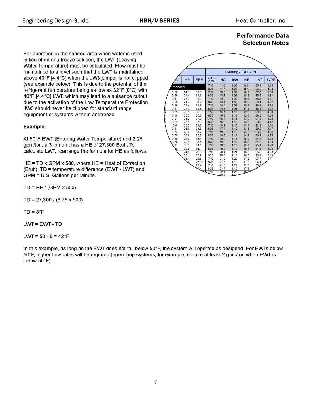
For operation in the shaded area when water is used in lieu of an
Example:
At 50°F EWT (Entering Water Temperature) and 2.25 gpm/ton, a 3 ton unit has a HE of 27,300 Btuh. To calculate LWT, rearrange the formula for HE as follows:
HE = TD x GPM x 500, where HE = Heat of Extraction (Btuh); TD = temperature difference (EWT - LWT) and GPM = U.S. Gallons per Minute.
TD = HE / (GPM x 500)
TD = 27,300 / (6.75 x 500)
TD = 8°F
LWT = EWT - TD
LWT = 50 - 8 = 42°F
Performance Data
Selection Notes
AT 80/67°F |
|
|
| Heating - EAT 70°F |
| |||||
|
|
|
|
|
|
|
|
|
|
|
/Tot | kW |
| HR | EER | Airflow | HC | kW | HE | LAT | COP |
tio |
| CFM | ||||||||
|
|
|
|
|
|
|
|
|
|
|
recommended |
| 710 | 11.6 | 1.05 | 8.2 | 85.1 | 3.25 | |||
| 825 | 11.7 | 1.02 | 8.4 | 83.2 | 3.38 | ||||
|
|
|
|
| ||||||
3 | 0.58 |
| 24.1 | 38.3 | 710 | 13.6 | 1.09 | 10.1 | 87.8 | 3.66 |
5 | 0.59 |
| 24.4 | 38.3 | 825 | 13.8 | 1.06 | 10.3 | 85.5 | 3.81 |
3 | 0.57 |
| 24.3 | 39.2 | 710 | 14.2 | 1.09 | 10.7 | 88.5 | 3.81 |
5 | 0.58 |
| 24.7 | 39.2 | 825 | 14.4 | 1.06 | 10.9 | 86.1 | 3.97 |
2 | 0.56 |
| 24.4 | 39.8 | 710 | 14.4 | 1.09 | 10.9 | 88.8 | 3.86 |
5 | 0.57 |
| 24.7 | 39.8 | 825 | 14.6 | 1.06 | 11.1 | 86.3 | 4.02 |
6 | 0.65 |
| 25.1 | 35.3 | 710 | 16.1 | 1.15 | 12.3 | 90.9 | 4.08 |
8 | 0.66 |
| 25.5 | 35.3 | 825 | 16.2 | 1.12 | 12.6 | 88.2 | 4.25 |
5 | 0.61 |
| 25.2 | 37.9 | 710 | 16.7 | 1.15 | 13.0 | 91.8 | 4.25 |
8 | 0.62 |
| 25.5 | 37.9 | 825 | 16.9 | 1.12 | 13.3 | 89.0 | 4.42 |
5 | 0.6 |
| 25.2 | 38.3 | 710 | 16.9 | 1.16 | 13.2 | 92.1 | 4.30 |
8 | 0.61 |
| 25.6 | 38.3 | 825 | 17.1 | 1.12 | 13.5 | 89.2 | 4.47 |
8 | 0.74 |
| 25.2 | 30.7 | 710 | 18.3 | 1.18 | 14.5 | 93.9 | 4.56 |
0 | 0.75 |
| 25.6 | 30.7 | 825 | 18.5 | 1.14 | 14.8 | 90.8 | 4.75 |
7 | 0.69 |
| 25.3 | 33.4 | 710 | 19.1 | 1.18 | 15.2 | 94.8 | 4.73 |
0 | 0.70 |
| 25.6 | 33.4 | 825 | 19.3 | 1.15 | 15.5 | 91.6 | 4.93 |
7 | 0.67 |
| 25.3 | 34.1 | 710 | 19.3 | 1.18 | 15.4 | 95.1 | 4.78 |
0 | 0.68 |
| 25.6 | 34.1 | 825 | 19.5 | 1.15 | 15.7 | 91.9 | 4.98 |
|
|
|
|
|
|
|
|
|
|
|
0 | 0.85 |
| 24.8 | 25.9 | 710 | 20.4 | 1.21 | 16.5 | 96.6 | 4.93 |
3 | 0.86 |
| 25.1 | 25.9 | 825 | 20.6 | 1.18 | 16.8 | 93.2 | 5.13 |
9 | 0.78 |
| 25.1 | 28.6 | 710 | 21.2 | 1.22 | 17.3 | 97.7 | 5.10 |
2 | 0.80 |
| 25.4 | 28.6 | 825 | 21.5 | 1.18 | 17.6 | 94.1 | 5.31 |
9 | 0.77 |
| 25.1 | 29.4 | 710 | 21.5 | 1.22 | 17.5 | 98.0 | 5.15 |
1 | 0.78 |
| 25.5 | 29.4 | 825 | 21.7 | 1.19 | 17.8 | 94.3 | 5.36 |
2 | 0.97 |
| 24.0 | 21.4 | 710 | 22.4 | 1.23 | 18.4 | 99.2 | 5.35 |
4 | 0.98 |
| 24.3 | 21.4 | 825 | 22.7 | 1.19 | 18.8 | 95.4 | 5.57 |
In this example, as long as the EWT does not fall below 50°F, the system will operate as designed. For EWTs below 50°F, higher flow rates will be required (open loop systems, for example, require at least 2 gpm/ton when EWT is below 50°F).
7