B. Continue Adding Vent Components
WARNING! Risk of Fire! Installation of this appliance may require the use of heat shield
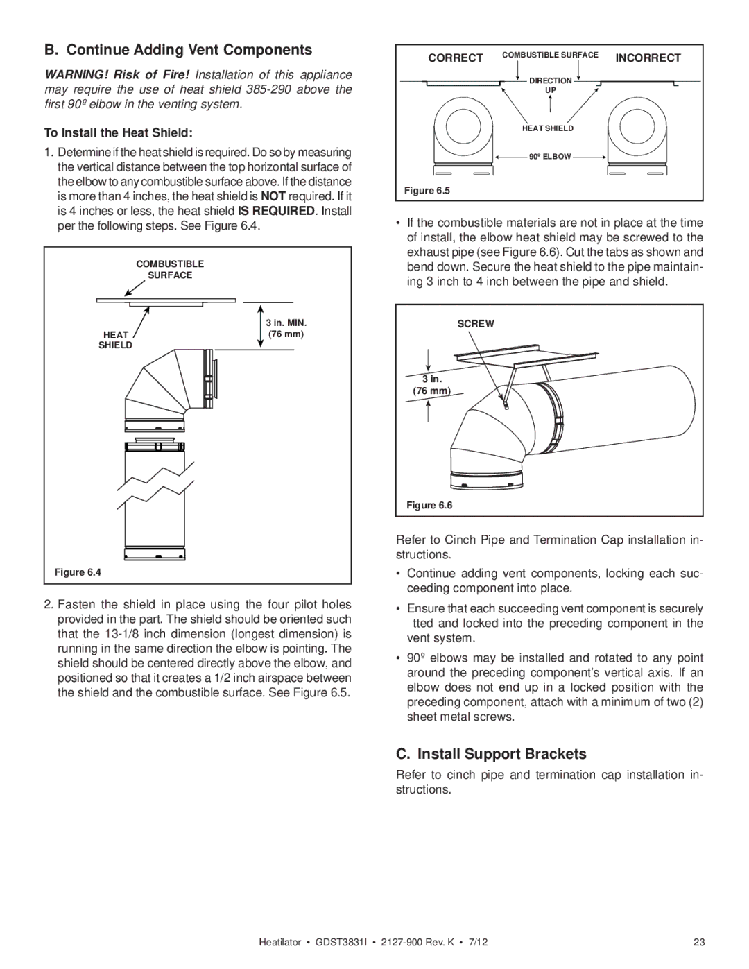
To Install the Heat Shield:
1.Determine if the heat shield is required. Do so by measuring the vertical distance between the top horizontal surface of the elbow to any combustible surface above. If the distance is more than 4 inches, the heat shield is NOT required. If it is 4 inches or less, the heat shield IS REQUIRED. Install per the following steps. See Figure 6.4.
|
|
|
|
| COMBUSTIBLE | |||||||||||||||||
|
|
|
|
| SURFACE | |||||||||||||||||
|
|
|
|
|
|
|
|
|
|
|
|
|
|
|
|
|
|
|
|
|
|
|
|
|
|
|
|
|
|
|
|
|
|
|
|
|
|
|
|
|
|
|
| 3 in. MIN. | |
|
|
|
|
|
|
|
|
|
|
|
|
|
|
|
|
|
|
|
|
| ||
| HEAT |
|
|
|
|
|
|
|
|
|
|
|
|
|
|
|
| (76 mm) | ||||
| SHIELD |
|
|
|
|
|
|
|
|
|
|
|
|
|
|
|
|
|
| |||
|
|
|
|
|
|
|
|
|
|
|
|
|
|
|
|
|
|
|
|
|
|
|
|
|
|
|
|
|
|
|
|
|
|
|
|
|
|
|
|
|
|
|
|
|
|
|
|
|
|
|
|
|
|
|
|
|
|
|
|
|
|
|
|
|
|
|
|
|
|
|
|
|
|
|
|
|
|
|
|
|
|
|
|
|
|
|
|
|
|
|
|
|
|
|
|
|
|
|
|
|
|
|
|
|
|
|
|
|
|
|
|
|
|
|
|
|
|
|
|
|
|
|
|
|
|
|
|
|
|
|
|
|
|
|
|
|
|
|
|
|
|
|
|
|
|
|
|
|
|
|
|
|
|
|
|
|
|
|
|
|
|
|
|
|
|
|
|
|
|
|
|
|
|
|
|
|
|
|
|
|
|
|
|
|
|
|
|
|
|
|
|
|
|
|
|
|
|
|
|
|
|
|
|
|
|
|
|
|
|
|
|
|
|
|
|
|
|
|
|
|
|
|
|
|
|
|
|
|
|
|
|
|
|
|
|
|
|
|
|
|
|
|
|
|
|
|
|
|
|
|
|
|
|
|
|
|
|
|
|
|
|
|
|
|
|
|
|
|
|
|
|
|
|
|
|
|
|
|
|
|
|
|
|
|
|
|
|
|
|
|
|
|
|
|
|
|
|
|
|
|
|
|
|
|
|
|
|
|
|
|
|
|
|
|
|
|
|
|
|
|
|
|
|
|
|
|
|
|
|
|
|
|
|
|
|
|
|
|
|
|
|
|
|
|
|
|
|
|
|
|
|
|
|
|
|
|
|
|
|
|
|
|
|
|
|
|
|
|
|
|
|
|
|
|
|
|
|
|
|
|
|
|
|
|
|
|
|
|
|
|
|
|
|
|
|
|
|
|
|
|
|
|
|
|
|
|
|
|
|
|
|
|
|
|
|
|
|
|
|
|
|
|
|
|
|
|
|
|
|
|
|
|
|
|
|
|
|
|
|
|
|
|
|
|
|
|
|
|
|
|
|
|
|
|
|
|
|
|
|
|
|
|
|
|
|
|
|
|
|
|
|
|
|
|
|
|
|
|
|
|
|
|
Figure 6.4
2.Fasten the shield in place using the four pilot holes provided in the part. The shield should be oriented such that the
CORRECT | COMBUSTIBLE SURFACE | INCORRECT |
| ||
| DIRECTION |
|
| UP |
|
| HEAT SHIELD |
|
| 90º ELBOW |
|
Figure 6.5 |
|
|
•If the combustible materials are not in place at the time of install, the elbow heat shield may be screwed to the exhaust pipe (see Figure 6.6). Cut the tabs as shown and bend down. Secure the heat shield to the pipe maintain- ing 3 inch to 4 inch between the pipe and shield.
SCREW |
3 in. |
(76 mm) |
Figure 6.6 |
Refer to Cinch Pipe and Termination Cap installation in- structions.
•Continue adding vent components, locking each suc- ceeding component into place.
•Ensure that each succeeding vent component is securely fitted and locked into the preceding component in the vent system.
•90º elbows may be installed and rotated to any point around the preceding component’s vertical axis. If an elbow does not end up in a locked position with the preceding component, attach with a minimum of two (2) sheet metal screws.
C. Install Support Brackets
Refer to cinch pipe and termination cap installation in- structions.
Heatilator • GDST3831I • | 23 |