|
|
|
| IGNITION | INTERMITTENT | |
|
|
|
| MODULE 3 VAC | PILOT IGNITOR | |
|
|
|
| I |
|
|
|
|
|
| S |
|
|
|
|
| TRANSFORMER | ORANGE |
| |
|
|
|
| 3 VAC |
| |
|
|
|
|
|
| |
| HOT | NEUTRAL |
|
| WHITE |
|
|
| GROUND TO |
| |||
| PLUG IN | FIREPLACE |
| |||
|
| CHASSIS |
| |||
|
|
| BLACK |
| ||
|
|
|
|
|
| |
|
|
|
| RED |
|
|
| BATTERY PACK |
|
| WIRES |
|
|
|
|
| (TO BROWN) |
|
| |
|
|
|
|
|
| |
|
|
|
|
| ORANGE | GREEN |
|
|
|
| THERMOSTAT |
|
|
|
|
| WIRE ASSEMBLY |
|
| |
|
|
|
|
| VALVE |
|
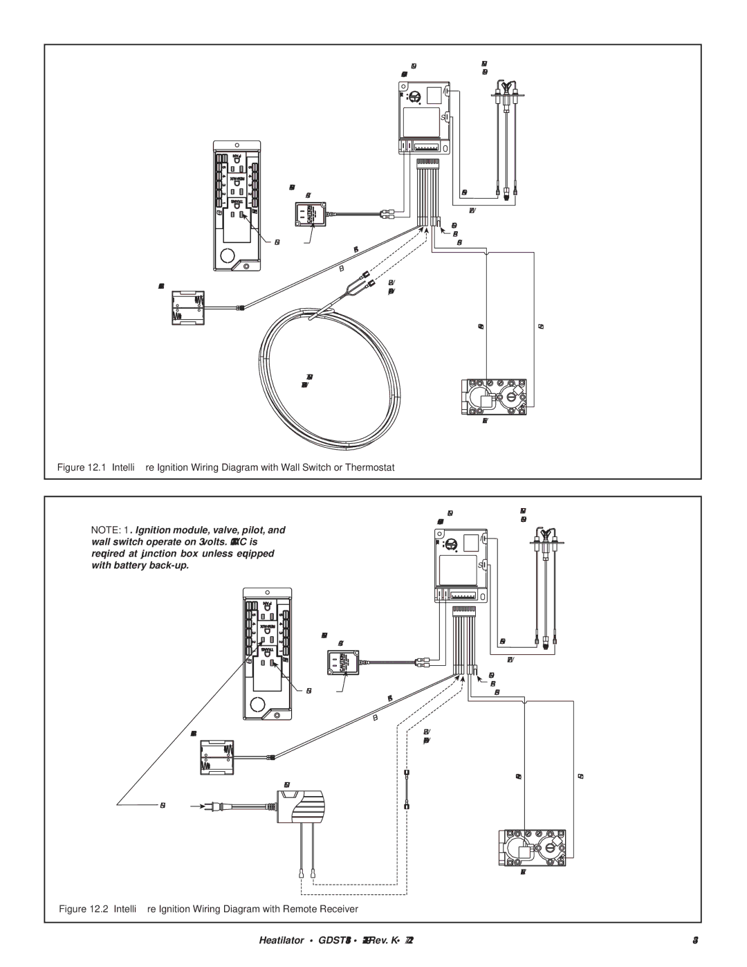
Figure 12.1 | Intellifire Ignition Wiring Diagram with Wall Switch or Thermostat |
|
| |||
|
|
|
| IGNITION | INTERMITTENT | |
|
|
|
| MODULE 3 VAC | PILOT IGNITOR | |
NOTE: 1. Ignition module, valve, pilot, and wall switch operate on 3 volts. 120 VAC is required at junction box unless equipped with battery
![]()
![]() I
I![]()
![]()
![]()
S![]()
![]()
![]()
HOT | NEUTRAL |
BATTERY PACK
TRANSFORMER
3 VAC
PLUG IN | BLACK |
| |
| RED |
ORANGE
WHITE
GROUND TO
![]() FIREPLACE
FIREPLACE
CHASSIS
WIRES
(TO BROWN)
ORANGE
GREEN
REMOTE
PLUG IN ![]()
![]()
![]()
![]()
![]()
![]()
![]()
![]()
![]()
![]()
![]()
![]()
![]()
VALVE
Figure 12.2 Intellifire Ignition Wiring Diagram with Remote Receiver
Heatilator • GDST3831I • | 43 |