Model
|
| ||
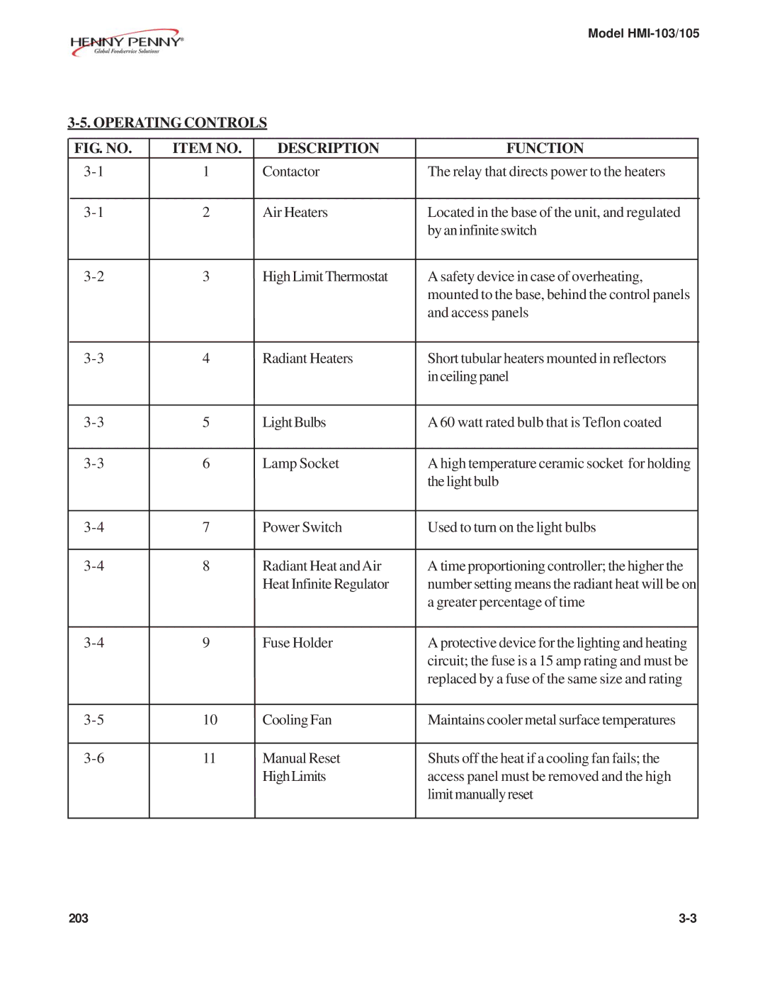
FIG. NO. | ITEM NO. | DESCRIPTION | FUNCTION |
1 | Contactor | The relay that directs power to the heaters | |
2 | Air Heaters | Located in the base of the unit, and regulated | |
|
|
| by an infinite switch |
3 | High Limit Thermostat | A safety device in case of overheating, | |
|
|
| mounted to the base, behind the control panels |
|
|
| and access panels |
4 | Radiant Heaters | Short tubular heaters mounted in reflectors | |
|
|
| in ceiling panel |
5 | LightBulbs | A 60 watt rated bulb that is Teflon coated | |
6 | Lamp Socket | A high temperature ceramic socket for holding | |
|
|
| the light bulb |
7 | Power Switch | Used to turn on the light bulbs | |
8 | Radiant Heat andAir | A time proportioning controller; the higher the | |
|
| Heat Infinite Regulator | number setting means the radiant heat will be on |
|
|
| a greater percentage of time |
9 | Fuse Holder | A protective device for the lighting and heating | |
|
|
| circuit; the fuse is a 15 amp rating and must be |
|
|
| replaced by a fuse of the same size and rating |
10 | Cooling Fan | Maintains cooler metal surface temperatures | |
|
|
|
|
11 | Manual Reset | Shuts off the heat if a cooling fan fails; the | |
|
| HighLimits | access panel must be removed and the high |
|
|
| limitmanuallyreset |
203 |
