Displacement Pump
NOTE: Packing Repair Kit 235703 is available. Refer- ence numbers of parts included in the kit are marked with an asterisk, i.e., (223*).
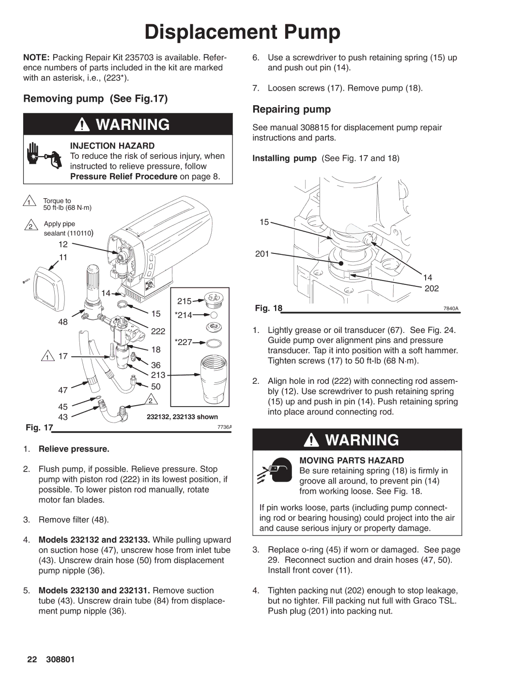
Removing pump (See Fig.17)
![]() WARNING
WARNING
INJECTION HAZARD
To reduce the risk of serious injury, when instructed to relieve pressure, follow Pressure Relief Procedure on page 8.
6.Use a screwdriver to push retaining spring (15) up and push out pin (14).
7.Loosen screws (17). Remove pump (18).
Repairing pump
See manual 308815 for displacement pump repair instructions and parts.
Installing pump (See Fig. 17 and 18)
1Torque to
50
2Apply pipe sealant (110110)
12
11
14
48
1 17
47
45
43
Fig. 17
215
15 *214
222
*227
18
36
213
![]() 50
50
2
232132, 232133 shown
7736A
15 ![]()
201 ![]()
14
202
Fig. 18 | 7840A | |
|
|
|
1.Lightly grease or oil transducer (67). See Fig. 24. Guide pump over alignment pins and pressure transducer. Tap it into position with a soft hammer. Tighten screws (17) to 50
2.Align hole in rod (222) with connecting rod assem- bly (12). Use screwdriver to push retaining spring (15) up and push in pin (14). Push retaining spring into place around connecting rod.
1.Relieve pressure.
2.Flush pump, if possible. Relieve pressure. Stop pump with piston rod (222) in its lowest position, if possible. To lower piston rod manually, rotate motor fan blades.
3.Remove filter (48).
4.Models 232132 and 232133. While pulling upward on suction hose (47), unscrew hose from inlet tube (43). Unscrew drain hose (50) from displacement pump nipple (36).
5.Models 232130 and 232131. Remove suction tube (43). Unscrew drain tube (84) from displace- ment pump nipple (36).
![]() WARNING
WARNING
MOVING PARTS HAZARD
Be sure retaining spring (18) is firmly in groove all around, to prevent pin (14) from working loose. See Fig. 18.
If pin works loose, parts (including pump connect- ing rod or bearing housing) could project into the air and cause serious injury or property damage.
3.Replace
4.Tighten packing nut (202) enough to stop leakage, but no tighter. Fill packing nut full with Graco TSL. Push plug (201) into packing nut.
22 308801