English

7. Crown molding cutting procedures

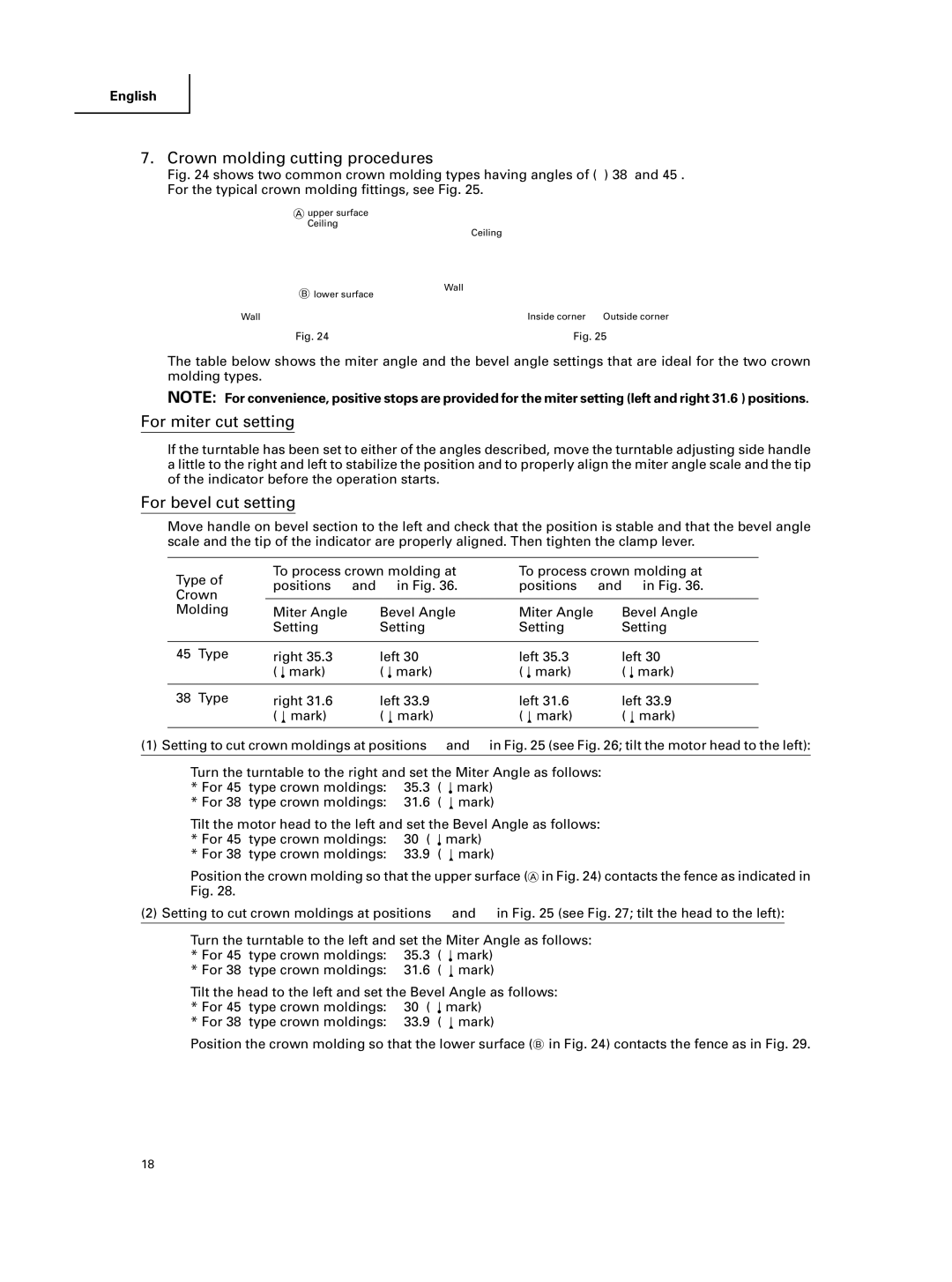
Fig. 24 shows two common crown molding types having angles of (θ) 38° and 45°. For the typical crown molding fittings, see Fig. 25.

upper surface

Ceiling


Ceiling


lower surface

Wall


1 2

3 4





Wall

Inside corner

Outside corner

Fig. 24

Fig. 25

The table below shows the miter angle and the bevel angle settings that are ideal for the two crown molding types.

NOTE: For convenience, positive stops are provided for the miter setting (left and right 31.6°) positions.

For miter cut setting

If the turntable has been set to either of the angles described, move the turntable adjusting side handle a little to the right and left to stabilize the position and to properly align the miter angle scale and the tip of the indicator before the operation starts.

For bevel cut setting

Move handle on bevel section to the left and check that the position is stable and that the bevel angle scale and the tip of the indicator are properly aligned. Then tighten the clamp lever.

Type of

Crown

Molding

To process crown molding at

To process crown molding at

positions 1 and 4 in Fig. 36.

positions 2 and 3 in Fig. 36.


Miter Angle

Bevel Angle

Miter Angle

Bevel Angle

Setting

Setting

Setting

Setting

45° Type

right 35.3°

left 30°

left 35.3°

left 30°


(


mark)

(


mark)

(


mark)

(


mark)


38° Type

right 31.6°

left 33.9°

left 31.6°

left 33.9°


(


mark)

(


mark)

(


mark)

(


mark)


(1)Setting to cut crown moldings at positions 1 and 4 in Fig. 25 (see Fig. 26; tilt the motor head to the left):

1 Turn the turntable to the right and set the Miter Angle as follows:

* For 45° type crown moldings:

35.3° (


mark)

* For 38° type crown moldings:

31.6° (


mark)


2Tilt the motor head to the left and set the Bevel Angle as follows:

* For 45° type crown moldings:

30° (


mark)

* For 38° type crown moldings:

33.9° (


mark)


3Position the crown molding so that the upper surface ( in Fig. 24) contacts the fence as indicated in Fig. 28.

(2)Setting to cut crown moldings at positions 2 and 3 in Fig. 25 (see Fig. 27; tilt the head to the left):

1Turn the turntable to the left and set the Miter Angle as follows:

* For 45° type crown moldings:

35.3° (


mark)

* For 38° type crown moldings:

31.6° (


mark)


2Tilt the head to the left and set the Bevel Angle as follows:

* For 45° type crown moldings:

30° (


mark)

* For 38° type crown moldings:

33.9° (


mark)


3Position the crown molding so that the lower surface ( in Fig. 24) contacts the fence as in Fig. 29.

18

Page 18
Image 18
Hitachi C 10FCE instruction manual Crown molding cutting procedures, For miter cut setting, For bevel cut setting

C 10FCE specifications

The Hitachi C 10FCE is a powerful and versatile 10-inch sliding compound miter saw designed to meet the needs of both professional contractors and serious DIY enthusiasts. Renowned for its precision and ease of use, this tool is engineered to deliver accurate cuts while offering a range of features that enhance its functionality.

One of the standout features of the C 10FCE is its 15-amp motor, which delivers a robust performance capable of cutting through a variety of materials, including hardwoods, softwoods, and engineered woods. The motor provides a no-load speed of 5,000 RPM, allowing for swift and efficient cutting tasks. The saw is equipped with a unique 0 to 52-degree miter angle range, providing versatility for making precise crosscuts at various angles. The dual-bevel functionality allows users to make beveled cuts in both directions, amplifying the tool’s adaptability for a wide range of projects.

The C 10FCE is also equipped with a laser guide system, which aids in ensuring accuracy by projecting a line on the workpiece where the cut will occur. This feature is particularly useful for achieving clean and precise cuts, reducing the likelihood of errors. Additionally, the saw boasts a large, robust table that provides ample support for larger workpieces, enhancing stability during use.

Durability is an important characteristic of the Hitachi C 10FCE. The saw features a rigid base that minimizes vibration and maximizes stability, resulting in smoother operation. The model is constructed with high-quality materials, ensuring longevity and consistent performance over time.

Safety is another key aspect integrated into the C 10FCE design. The saw includes a blade guard that covers the upper portion of the blade while in operation, protecting users from accidental contact. The electric brake system stops the blade quickly after the trigger is released, further enhancing user safety.

In conclusion, the Hitachi C 10FCE sliding compound miter saw is a feature-rich tool combining power, precision, and safety. With its reliable motor, versatile cutting angles, laser guide system, and durable construction, it stands as an ideal choice for anyone looking to tackle complex cutting tasks with confidence and accuracy. Whether for intricate trim work or larger construction projects, the C 10FCE is built to handle a diverse range of applications efficiently.