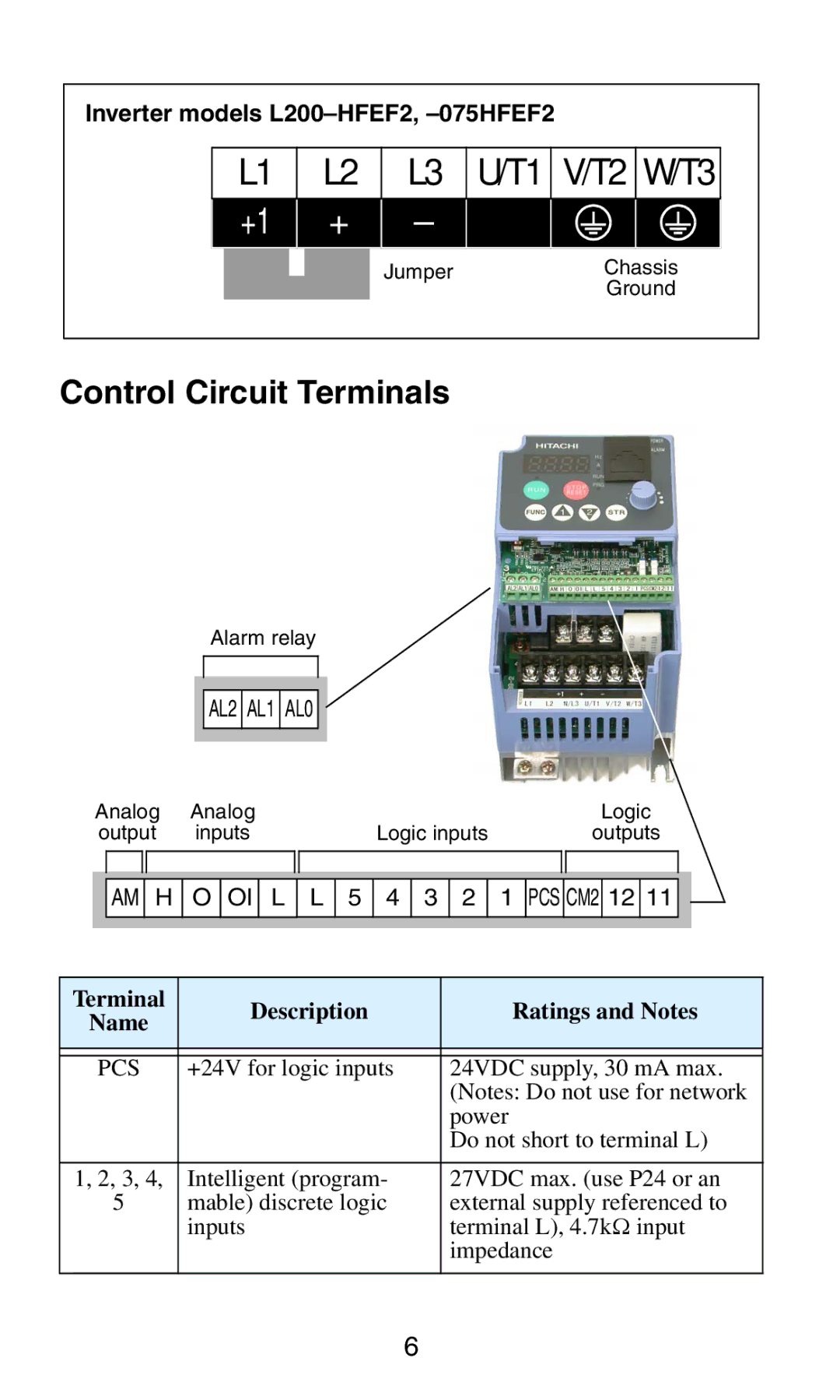
Inverter models
| L1 |
| L2 |
| L3 | U/T1 | V/T2 | W/T3 | |
| +1 |
|
| + |
| – |
|
|
|
|
|
|
|
|
| Jumper |
| Chassis | |
|
|
|
|
|
|
|
| Ground | |
Control Circuit Terminals
Alarm relay
AL2 AL1 AL0
Analog | Analog |
| Logic |
output | inputs | Logic inputs | outputs |
![]()
![]() AM
AM ![]() H O OI L L 5
H O OI L L 5
4 3 2
1 PCS CM2 12 11 ![]()
![]()
Terminal | Description | Ratings and Notes | |
Name | |||
|
| ||
|
|
| |
|
|
| |
PCS | +24V for logic inputs | 24VDC supply, 30 mA max. | |
|
| (Notes: Do not use for network | |
|
| power | |
|
| Do not short to terminal L) | |
|
|
| |
1, 2, 3, 4, | Intelligent (program- | 27VDC max. (use P24 or an | |
5 | mable) discrete logic | external supply referenced to | |
| inputs | terminal L), 4.7kΩ input | |
|
| impedance | |
|
|
|
6