ELECTRICAL DATA
|
|
|
| Rated Amps |
| Fuse Size or |
| ||
Total |
| Kilowatts Per Phase | 3 Phase |
| 1 Phase | Circuit Size | 90°C Copper | ||
Volts / Hz / Ph |
| Circuit Breaker Size * | |||||||
KW |
| Amps Per Line Wire | Amps | (Amps) | Wire Size | ||||
|
| (Amps) | |||||||
| L1 - L2 L2 - L3 L1 - L3 L1 | L2 | L3 | ||||||
|
|
|
|
| |||||
|
|
|
|
|
| ||||
7.5 | 208 / 60 / 1 |
|
|
|
|
|
| 36 | 50 | 50 | 8 |
7.5 | 240 / 60 / 1 |
|
|
|
|
|
| 31 | 45 | 45 | 8 |
7.5 | 208 / 60 / 3 | 2.5 | 2.5 | 2.5 | 21 | 21 | 21 |
| 30 | 30 | 10 |
7.5 | 240 / 60 / 3 | 2.5 | 2.5 | 2.5 | 18 | 18 | 18 |
| 25 | 25 | 14 |
7.5 | 480 / 60 / 3 | 2.5 | 2.5 | 2.5 | 9 | 9 | 9 |
| 15 | 15 | 16 |
10 | 208 / 60 / 1 |
|
|
|
|
|
| 48 | 60 | 60 | 8 |
10 | 240 / 60 / 1 |
|
|
|
|
|
| 42 | 60 | 60 | 8 |
10 | 208 / 60 / 3 | 3.3 | 3.3 | 3.3 | 28 | 28 | 28 |
| 35 | 35 | 10 |
|
|
|
|
|
|
|
|
|
|
|
|
10 | 240 / 60 / 3 | 3.3 | 3.3 | 3.3 | 24 | 24 | 24 |
| 35 | 35 | 10 |
|
|
|
|
|
|
|
|
|
|
|
|
10 | 480 / 60 / 3 | 3.3 | 3.3 | 3.3 | 12 | 12 | 12 |
| 15 | 15 | 16 |
|
|
|
|
|
|
|
|
|
|
|
|
15 | 208 / 60 / 1 |
|
|
|
|
|
| 72 | 90 | 90 | 6 |
15 | 240 / 60 / 1 |
|
|
|
|
|
| 63 | 90 | 90 | 6 |
15 | 208 / 60 / 3 | 5 | 5 | 5 | 42 | 42 | 42 |
| 60 | 60 | 8 |
15 | 240 / 60 / 3 | 5 | 5 | 5 | 36 | 36 | 36 |
| 50 | 50 | 8 |
15 | 480 / 60 / 3 | 5 | 5 | 5 | 18 | 18 | 18 |
| 25 | 25 | 14 |
|
|
|
|
|
|
|
|
|
| * Dual Element |
|
|
|
|
|
|
|
|
|
|
| Inverse Time Circuit Breaker |
|
Circuit Size (Minimum) & Fuse/Circuit Breaker Size (Maximum) compiled in accordance with the National Electrical Code ANSI/NFPA 70 (latest edition).
PLUMBING CONNECTIONS
WARNING: PLUMBING CONNECTIONS MUST COMPLY WITH APPLICABLE SANITARY, SAFETY AND PLUMBING CODES.
1.Connect the water supply line to the two 3/8" copper tube inlets as identified at the rear of the steamer.
2.Install the line strainer provided in the steam generator fill line.
•Provide a manual shutoff valve convenient to the steamer for descaling.
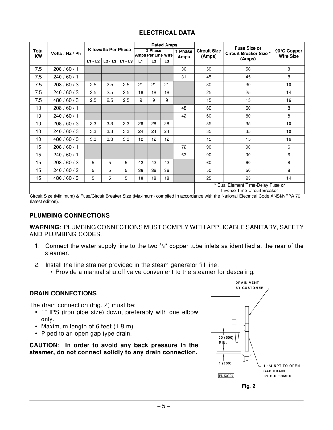
DRAIN VENT
BY CUSTOMER
DRAIN CONNECTIONS
The drain connection (Fig. 2) must be:
•1" IPS (iron pipe size) down, preferably with one elbow only.
•Maximum length of 6 feet (1.8 m).
•Piped to an open gap type drain.
CAUTION: In order to avoid any back pressure in the steamer, do not connect solidly to any drain connection.
20(500) MIN .
2 (500)
1 1/4 NPT TO OPEN
GAP DRAIN
BY CUSTOMER
Fig. 2
– 5 –