SECTION 2 – DEFINITIONS
2-1. Symbols And Definitions
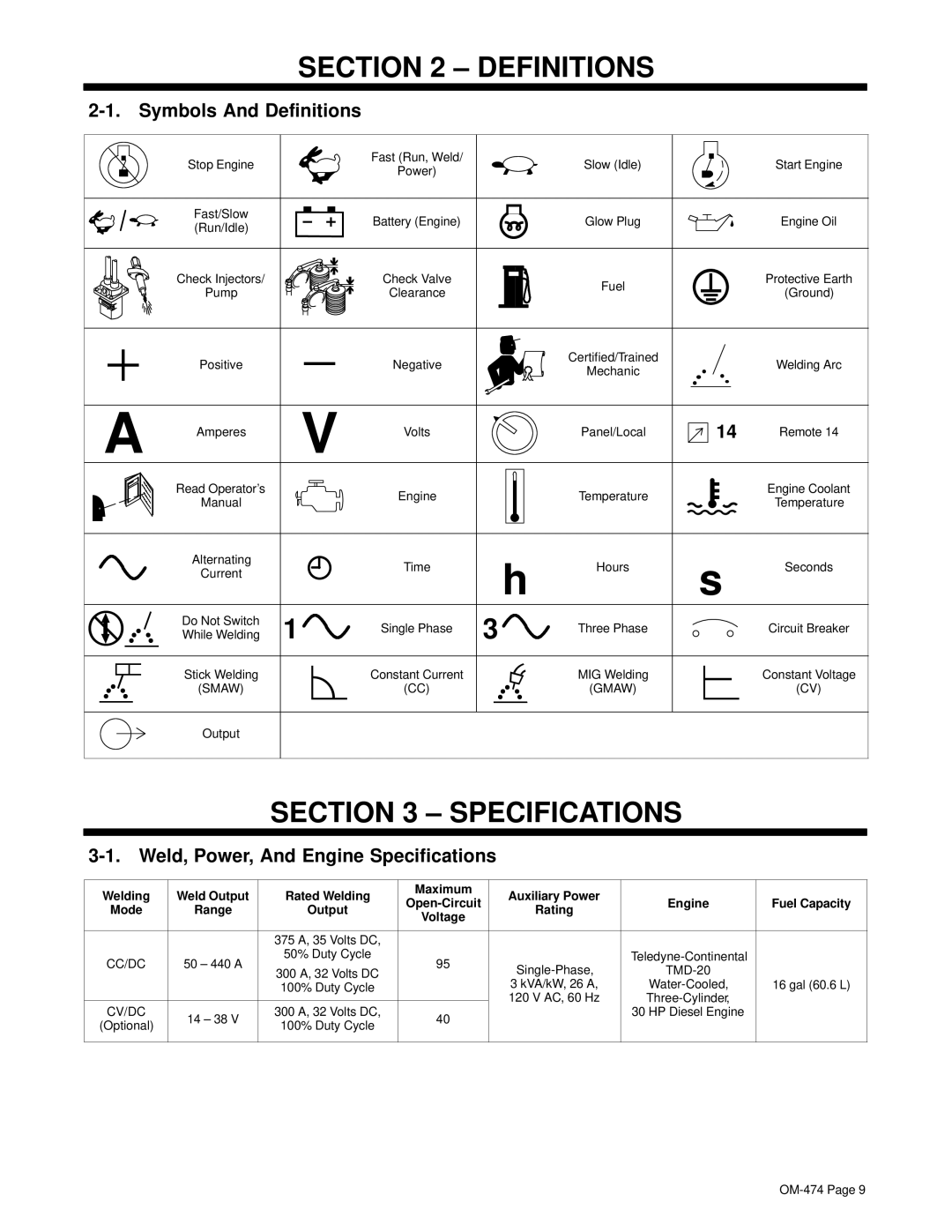
| Stop Engine |
| Fast (Run, Weld/ |
| Slow (Idle) |
| Start Engine |
|
| Power) |
|
| |||
|
|
|
|
|
|
| |
| Fast/Slow |
| Battery (Engine) |
| Glow Plug |
| Engine Oil |
| (Run/Idle) |
|
|
| |||
|
|
|
|
|
|
| |
| Check Injectors/ |
| Check Valve |
| Fuel |
| Protective Earth |
| Pump |
| Clearance |
|
| (Ground) | |
|
|
|
|
| |||
| Positive |
| Negative |
| Certified/Trained |
| Welding Arc |
|
|
| Mechanic |
| |||
A |
| V |
|
|
|
| |
Amperes | Volts |
| Panel/Local | 14 | Remote 14 | ||
|
|
| |||||
| Read Operator’s | G | Engine |
| Temperature |
| Engine Coolant |
| Manual |
|
| Temperature | |||
| 1 |
|
|
|
| ||
| Alternating |
| Time | h | Hours | s | Seconds |
| Current |
| |||||
|
|
|
|
| |||
|
|
|
|
|
|
| |
| Do Not Switch | 1 | Single Phase | 3 | Three Phase |
| Circuit Breaker |
| While Welding |
| |||||
| Stick Welding |
| Constant Current |
| MIG Welding |
| Constant Voltage |
| (SMAW) |
| (CC) |
| (GMAW) |
| (CV) |
| Output |
|
|
|
|
|
|
SECTION 3 – SPECIFICATIONS
3-1. Weld, Power, And Engine Specifications
Welding | Weld Output | Rated Welding | Maximum | Auxiliary Power |
|
| |
Engine | Fuel Capacity | ||||||
Mode | Range | Output | Rating | ||||
Voltage |
|
| |||||
|
|
|
|
|
| ||
|
|
|
|
|
|
| |
|
| 375 A, 35 Volts DC, |
|
|
|
| |
CC/DC | 50 – 440 A | 50% Duty Cycle | 95 |
| |||
300 A, 32 Volts DC |
| ||||||
|
|
|
| ||||
|
| 100% Duty Cycle |
| 3 kVA/kW, 26 A, | 16 gal (60.6 L) | ||
|
|
|
| 120 V AC, 60 Hz |
| ||
|
|
|
|
| |||
CV/DC | 14 – 38 V | 300 A, 32 Volts DC, | 40 |
| 30 HP Diesel Engine |
| |
(Optional) | 100% Duty Cycle |
|
|
| |||
|
|
|
|
| |||
|
|
|
|
|
|
|