4-5. Connecting To Weld Output Terminals
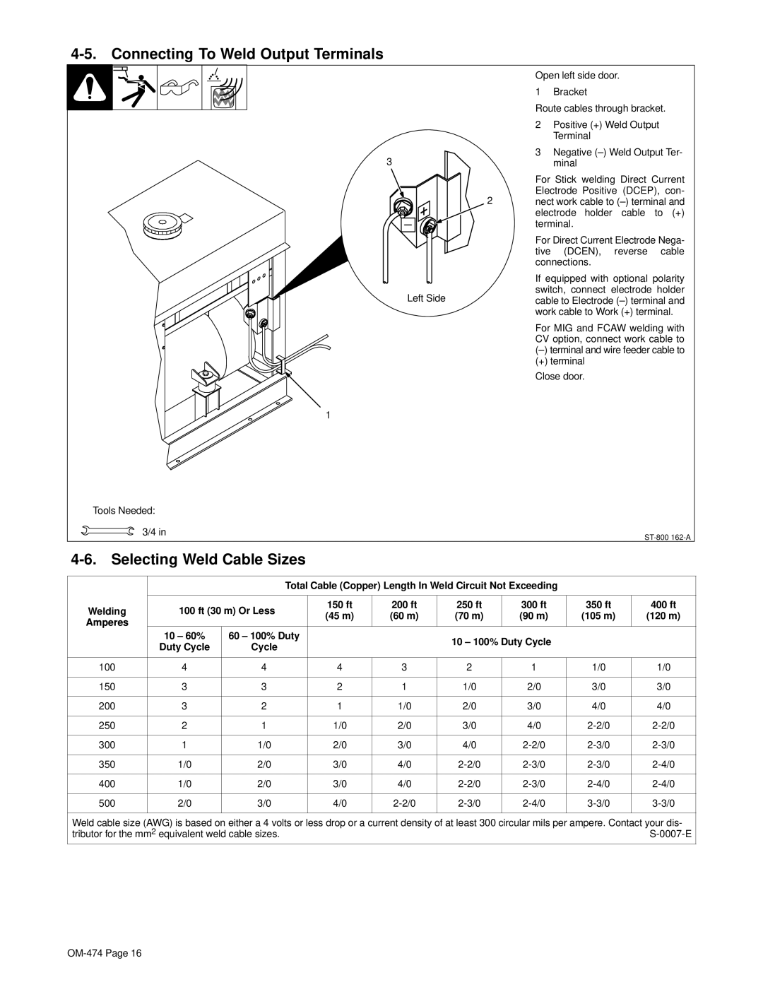
Open left side door.
1 Bracket
Route cables through bracket.
2 Positive (+) Weld Output
Terminal
3 | Negative |
3 | minal |
For Stick welding Direct Current Electrode Positive (DCEP), con-
2 nect work cable to
For Direct Current Electrode Nega- tive (DCEN), reverse cable connections.
If equipped with optional polarity switch, connect electrode holder
Left Sidecable to Electrode
For MIG and FCAW welding with CV option, connect work cable to
(+) terminal
Close door.
1
Tools Needed:
| 3/4 in |
|
|
|
|
|
|
| ||
|
|
|
|
|
|
|
|
|
| |
|
|
|
|
|
|
|
| |||
|
|
|
|
|
|
|
|
|
|
|
|
|
| Total Cable (Copper) Length In Weld Circuit Not Exceeding |
|
|
| ||||
|
|
|
|
|
|
|
|
|
|
|
Welding |
| 100 ft (30 m) Or Less | 150 ft | 200 ft | 250 ft | 300 ft | 350 ft | 400 ft |
| |
| (45 m) | (60 m) | (70 m) | (90 m) | (105 m) | (120 m) |
| |||
Amperes |
|
|
|
| ||||||
|
|
|
|
|
|
|
|
|
| |
|
| 10 – 60% | 60 – 100% Duty |
|
| 10 – 100% Duty Cycle |
|
|
| |
|
| Duty Cycle | Cycle |
|
|
|
|
| ||
|
|
|
|
|
|
|
|
| ||
|
|
|
|
|
|
|
|
|
|
|
100 |
| 4 | 4 | 4 | 3 | 2 | 1 | 1/0 | 1/0 |
|
|
|
|
|
|
|
|
|
|
|
|
150 |
| 3 | 3 | 2 | 1 | 1/0 | 2/0 | 3/0 | 3/0 |
|
|
|
|
|
|
|
|
|
|
|
|
200 |
| 3 | 2 | 1 | 1/0 | 2/0 | 3/0 | 4/0 | 4/0 |
|
|
|
|
|
|
|
|
|
|
|
|
250 |
| 2 | 1 | 1/0 | 2/0 | 3/0 | 4/0 |
| ||
|
|
|
|
|
|
|
|
|
|
|
300 |
| 1 | 1/0 | 2/0 | 3/0 | 4/0 |
| |||
|
|
|
|
|
|
|
|
|
|
|
350 |
| 1/0 | 2/0 | 3/0 | 4/0 |
| ||||
|
|
|
|
|
|
|
|
|
|
|
400 |
| 1/0 | 2/0 | 3/0 | 4/0 |
| ||||
|
|
|
|
|
|
|
|
|
|
|
500 |
| 2/0 | 3/0 | 4/0 |
| |||||
|
|
|
|
|
|
|
|
|
|
|
Weld cable size (AWG) is based on either a 4 volts or less drop or a current density of at least 300 circular mils per ampere. Contact your dis-
tributor for the mm2 equivalent weld cable sizes. |