SECTION 4 – INSTALLATION
4-1. Installing Welding Generator
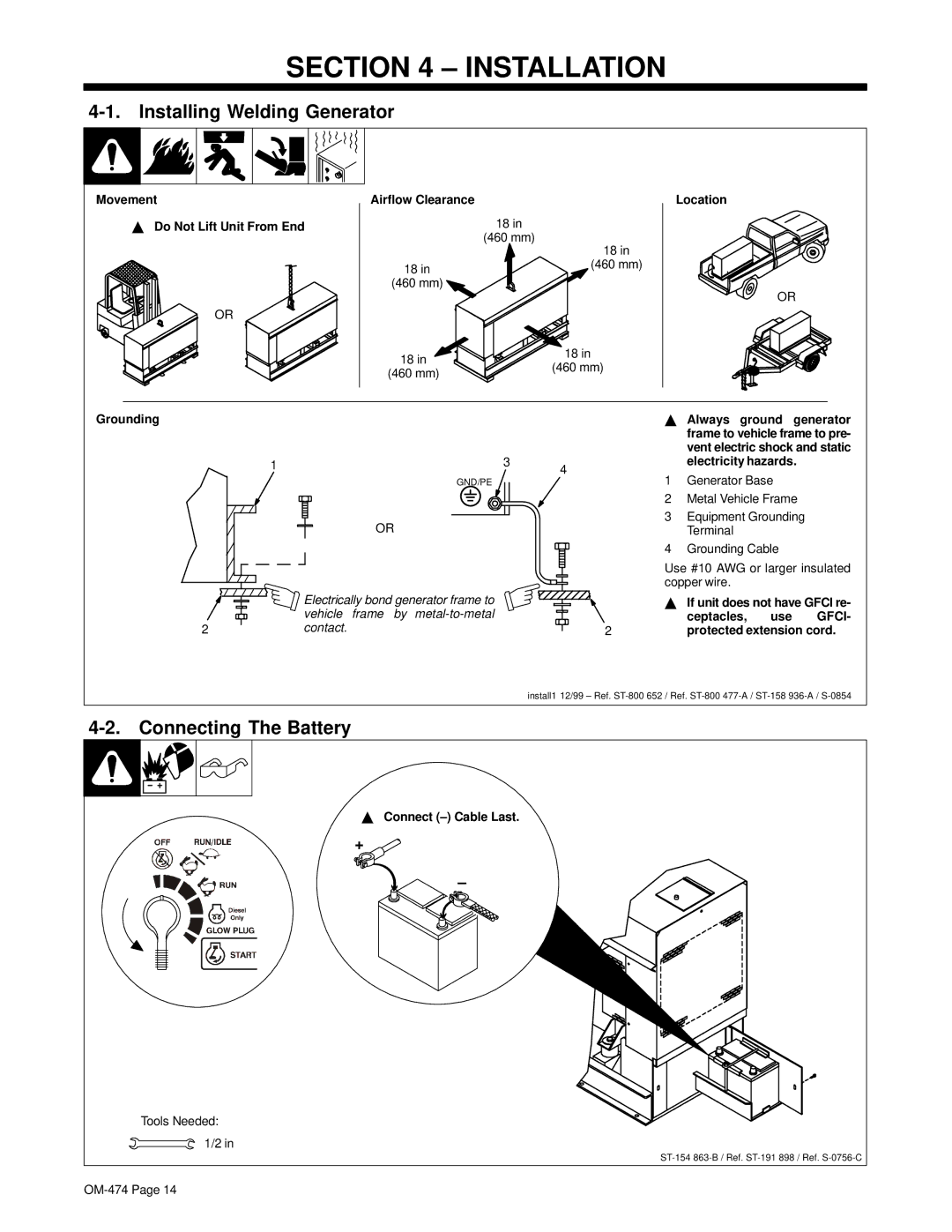
Movement
YDo Not Lift Unit From End
Airflow Clearance
18in
(460 mm)
Location
18 in
18 in
(460 mm)
OR
(460 mm) ![]()
18 in | 18 in | |
(460 mm) | ||
(460 mm) | ||
|
OR
Grounding |
|
| Y Always ground | generator | ||
|
|
|
| frame to vehicle frame to pre- | ||
|
|
|
| vent electric shock and static | ||
| 1 | 3 | 4 | electricity hazards. | ||
| GND/PE |
| 1 | Generator Base |
| |
|
|
| 2 | Metal Vehicle Frame | ||
| OR |
| 3 | Equipment Grounding | ||
|
|
| Terminal |
|
| |
|
|
| 4 | Grounding Cable |
| |
|
|
| Use #10 AWG or larger insulated | |||
|
|
| copper wire. |
|
| |
| Electrically bond generator frame to |
| Y If unit does not have GFCI re- | |||
| vehicle frame by |
|
| ceptacles, | use | GFCI- |
2 | contact. |
| 2 | protected extension cord. | ||
install1 12/99 – Ref.
4-2. Connecting The Battery
Y Connect |
+ |
– |
Tools Needed: |
1/2 in |