6-3. Connecting Optional Auxiliary Power Plant
Front
11 10
1 | F3 |
|
|
|
|
| |
2 |
| 240V |
|
F2 |
|
| |
|
|
| |
3 | 240V | 240V | 240V |
F1 |
|
| |
|
|
| |
| 120V | 120V |
|
1 3
9
4 | 5 | 6 | 7 | 8 |
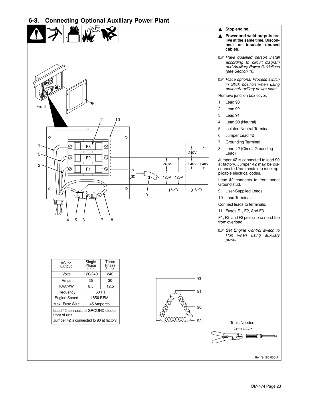
YStop engine.
YPower and weld outputs are live at the same time. Discon- nect or insulate unused cables.
.Have qualified person install according to circuit diagram and Auxiliary Power Guidelines (see Section 10).
.Place optional Process switch in Stick position when using optional auxiliary power plant.
Remove junction box cover.
1Lead 93
2Lead 92
3Lead 91
4Lead 90 (Neutral)
5Isolated Neutral Terminal
6Jumper Lead 42
7Grounding Terminal
8Lead 42 (Circuit Grounding Lead)
Jumper 42 is connected to lead 90 at factory. Jumper 42 may be dis- connected from neutral to meet ap- plicable electrical codes.
Lead 42 connects to front panel Ground stud.
9
10Load Terminals
Connect leads to terminals.
11 Fuses F1, F2, And F3
F1, F2, and F3 protect each load line from overload.
.Set Engine Control switch to Run when using auxiliary power.
AC | Single | Three | |
Phase | Phase | ||
Output | |||
| 1 | 3 | |
Volts | 120/240 | 240 | |
|
|
| |
Amps | 35 | 30 | |
KVA/KW | 8.5 | 12.5 | |
Frequency | 60 Hz | ||
Engine Speed | 1850 RPM | ||
|
| ||
Max. Fuse Size | 45 Amperes | ||
|
|
| |
Lead 42 connects to GROUND stud on front of unit.
Jumper 42 is connected to 90 at factory.
93
91
90 |
|
92 | Tools Needed: |
|
Ref.